118
Section G - Ice & Water Dispenser
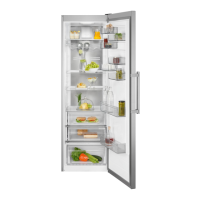
The control board is mounted on the front face and can be serviced by removing
the front face and removing the 4 screws holding the cover over the board on
standard models. On Icon model remove the two screws going form the front face
into the bottom of the retainer. Tip the retainer up and pull it out to remove the
control board (See Figure 35)
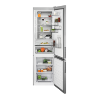
Current will be carried between the power board and the control board by a ribbon
connector (See Figure 36). You can check the cable with a Ohm meter one run at
a time if you suppect a bad cable.
The ribbon cable will be a replaceable part separate from the power and the control
board. To test and/or replace the ribbon, unplug the product and remove the front
face plate. Unplug the ribbon from the power board (See
figure 36) by pulling straight out. Remove the control
board from the front face plate and pull straight down on
the lock tab holding the ribbon into the control board.
(See Figure 37) Now you can unplug the ribbon from the
control board. The ribbon can be tested with a Multimeter
using the Ohm setting and test for continuity on each
pass of the ribbon. When installing a ribbon into the
power or the control board make sure the end of the
cable i installed so the contact point on the cable is
against the contact points on the board. Also clean the
end of the ribbon with a pencil eraser to get a good clean
surface for the connection.
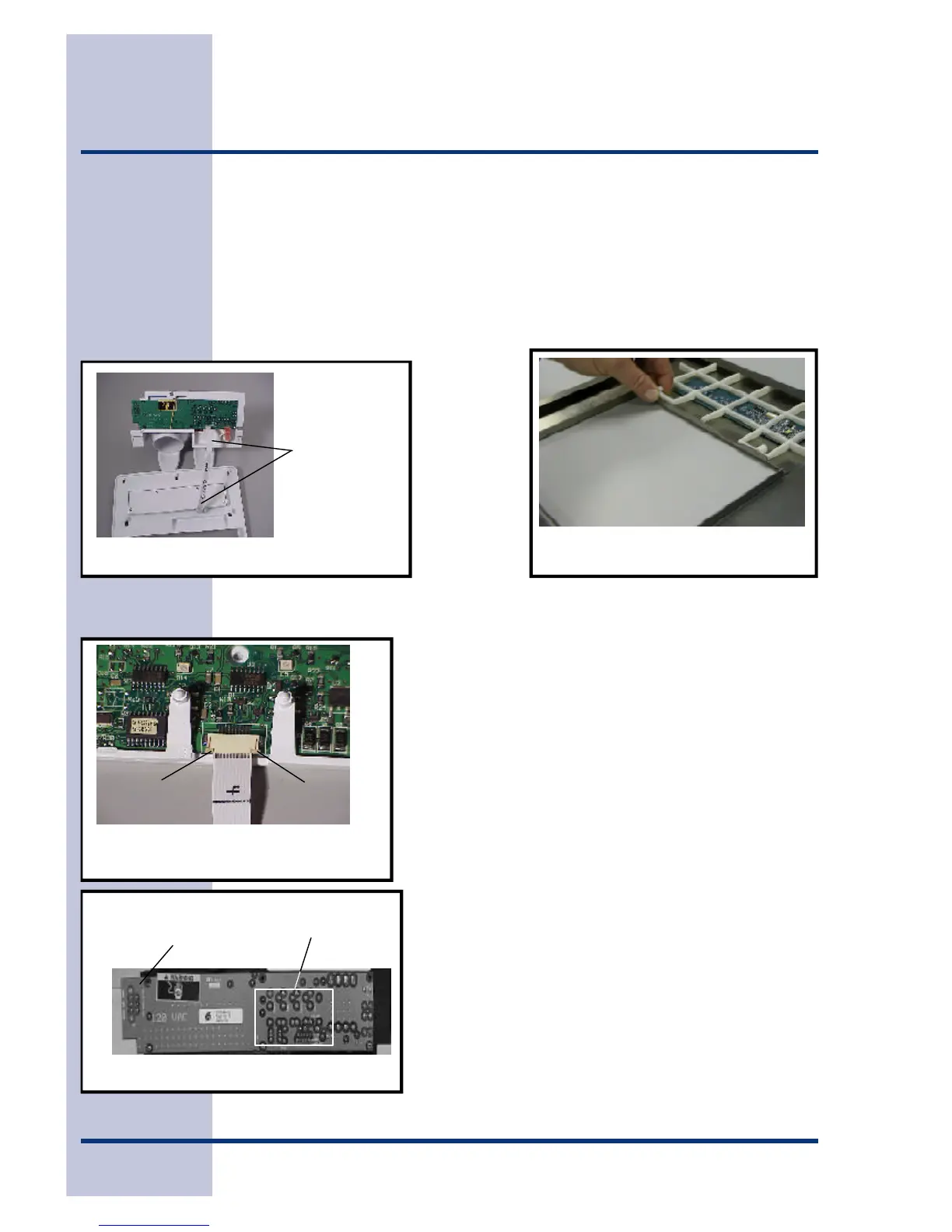
How To Test The Electronic Dispenser
Labeling was added to the face of the power board to
aide the servicer in testing of the control and power
board. (See Figure 38)
Figure 36
RIBBON CABLE
RUNNING FROM
POWER BOARD
TO CONTROL
BOARD
FIGURE 37
RIBBON NOT IN
LOCKING TAB
LOCKING TAB
FIGURE 38
CONNECTOR FOR DOOR
HARNESS TO CONNECT
TO POWER BOARD
AREA USED
FOR VOLTAGE
Figure 35
Lift up on power board support