SOI/DT 2010-03 dmm 45/78 599 72 84-41
11 TECHNICAL CHARACTERISTICS
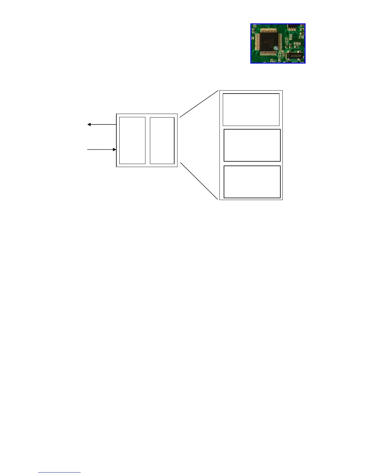
11.1 Electronic control system memory
11.1.1 General structure of the memory system
The system features a FLASH memory inside the micro-processor, which allows the recording of the
configuration data, the description of the cycle, the status of the appliance in the event of a power failure and
the alarms.
11.1.2 FLASH
This area of the memory contains the "firmware" code comprising the appliance functions:
Ö Control of electric loads (motor, pump, solenoid valves, etc.)
Ö Control of the sensors (pressure switches, motor speed, door status, etc.)
Ö management of the user interface;
Ö management of the serial port;
Ö management of power failures and alarms;
Ö Execution of the washing programme
Ö Power failure, i.e. the information necessary to restart the appliance in the event of a power failure:
- Selected cycle and options
- Current phase and sub-phase
Ö Appliance status, used to perform special cycles, such as:
- Electrical test (used on the assembly line)
- Continuous cycles (used in the factory workshop)
Ö Appliance configuration: the data contained in this portion of the memory defines the characteristics of the
model and is interpreted by the function software. The variables are as follows:
- Type of appliance (front-loader, top-loader, compact)
- Type of door interlock (PTC or instantaneous)
- Anti-flooding safety device
- Transmission ratio between drum pulley and motor pulley
- Structure of the washing group
- Power supply frequency (50 or 60 Hz)
- Type of PCB (horizontal or vertical buttons)
- Detergent dispenser (3 or 4 compartments)
- Final spin speed (600÷1,400 rpm)
Ö Identification of the appliance:
- Prod. No.
- ELC
- Serial Number
Ö Configuration of the user interface:
- Programmes on main selector
- Function of secondary selector (where featured)
- Number and functions of buttons
- LED functions
- Buzzer operation
External
asynchronous
serial port
FLASH RAM
μP
Power Fail and
appliance status
Appliance
configuration
Cycle
description