29
29. Door and door lock
12
438 9145-61/06
04.10
Service
Manual
Description
W365H, W375H
from machine No. 520/22807–
and 520/19487-19548
W3105H from machine No. 595/9041–
W3130H from machine No. 650/14355–
W3180H from machine No. 725/7909–
W3240H from machine No. 795/3770–
W3300H
General
The door lock part consists of the following:
• Door lock A41 that contains
-an actuator that locks the door lock and
which also has two built-in micro switches,
S4a and S4b. The actuator is bi-stable,
i.e., it has two stable positions: locked
door and unlocked door. The actuator
must receive a pulse to lock and unlock
the door lock. S4a and S4b are both
closed when the door is locked.
- micro switch S3 that is closed when the
door is closed.
- An emergency opening arm/emergency
opening button that can be used to open
the door lock in an emergency.
• Door lock control A31 that is situated in the
front control unit of the machine. This card
controls the door lock function and whether
the drum is empty and not rotating. It locks
and unlocks the door lock when the
programme unit requests door locking or
unlocking.
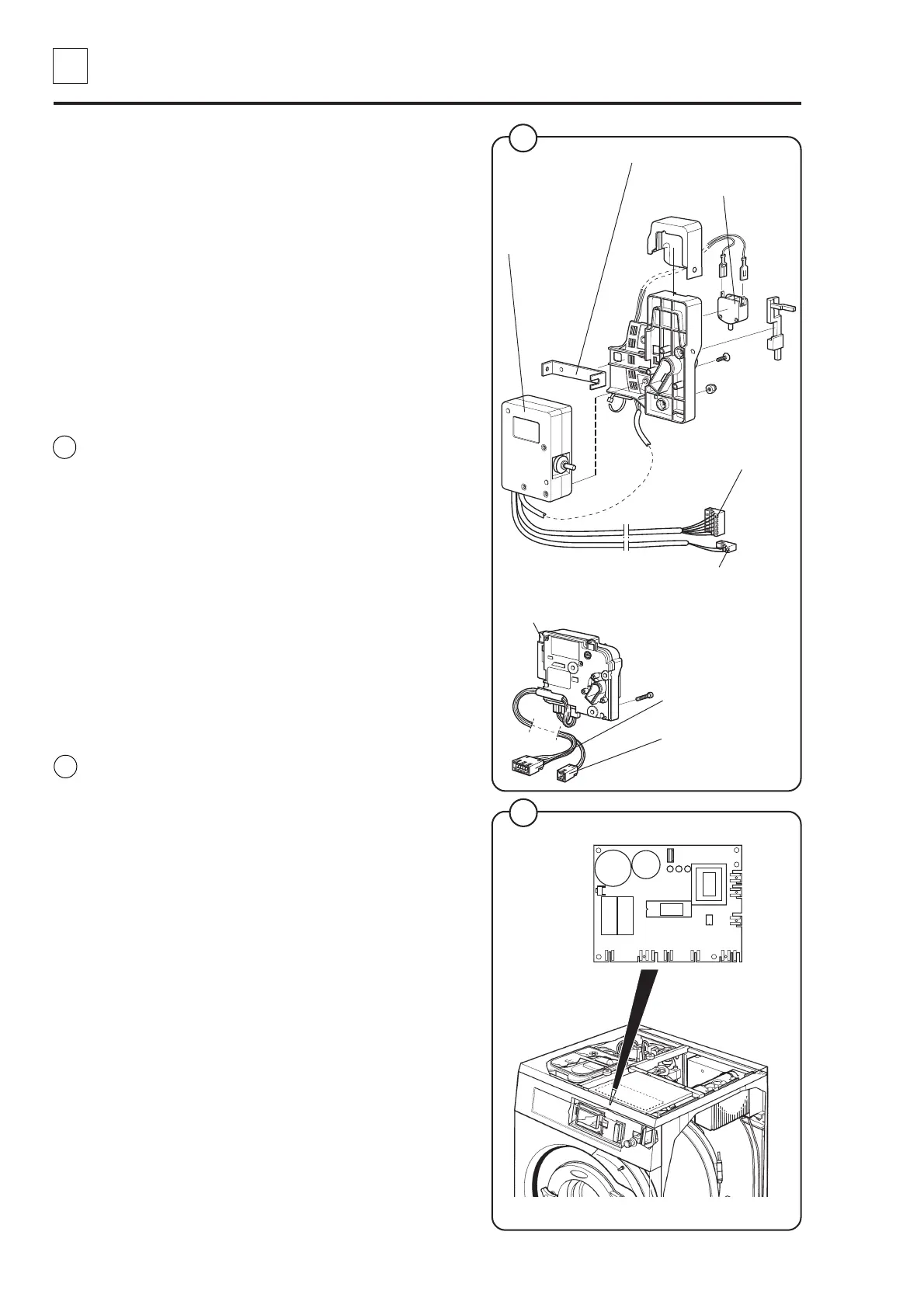
Fig.
13
Fig.
14
5928 5207
Actuator (with
micro switch S4a
and S4b)
Micro switch S3
X96 (to door lock control A31)
5368, 6112
Emergency opening arm
13
14
X5 (to I/O card 1 A11)
Emergency opening button
X96 (to door lock
control A31)
X5 (to I/O card 1
A11)
Door lock control A31
X96 X94 X95
X97X93
X92
X91
X90
1
1
1
1
1
1
1
1
IC6
(K2) (K1)
 Loading...