13
29
29. Door and door lock
438 9145-61/06
04.10
Service
Manual
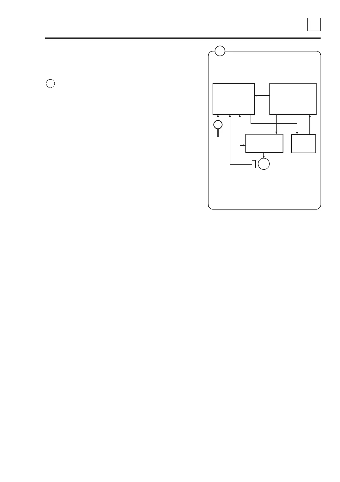
Function
The door lock locks the door
When the door is closed (closed door lock
switch S3), the programme unit may request
door locking by applying a voltage of 200-
240 V on door lock controller A31 input X92.
The following check is made by the A31 card
prior to locking of the door:
• No water in drum - input X93 from level
guard B2 is closed = 0 V
• Motor not engaged - input X94 from motor
control U1 open = 5 V
• Drum not rotating - pulse frequency on
input X95 from rotation sensor B3 less than
3 Hz.
When the above conditions are met, the card
A31 outputs a closing pulse on output X96 to
the door lock actuator/coil, which then locks the
door. The micro switches S4a and S4b in the
actuator/door lock are closed when the door is
locked. These micro switches feed voltage to:
• The output relays on I/O card 1. The relays
govern the machine’s drain and water valves
as well as heater switch-on.
• Interlock signal for motor control (input
X302 via I/O card 1) that releases the motor
start prevention state.
Programme operation is now possible.
Fig.
15
15
5931
Door lock
control
A31
Level
guard
B2
M1
Door lock
A41
Programme
unit A1
X92
X31
X96X95X93 X30X94
Motor
control
U1
Rotation sensor B3
(tacho)
X304
X302
X37
 Loading...