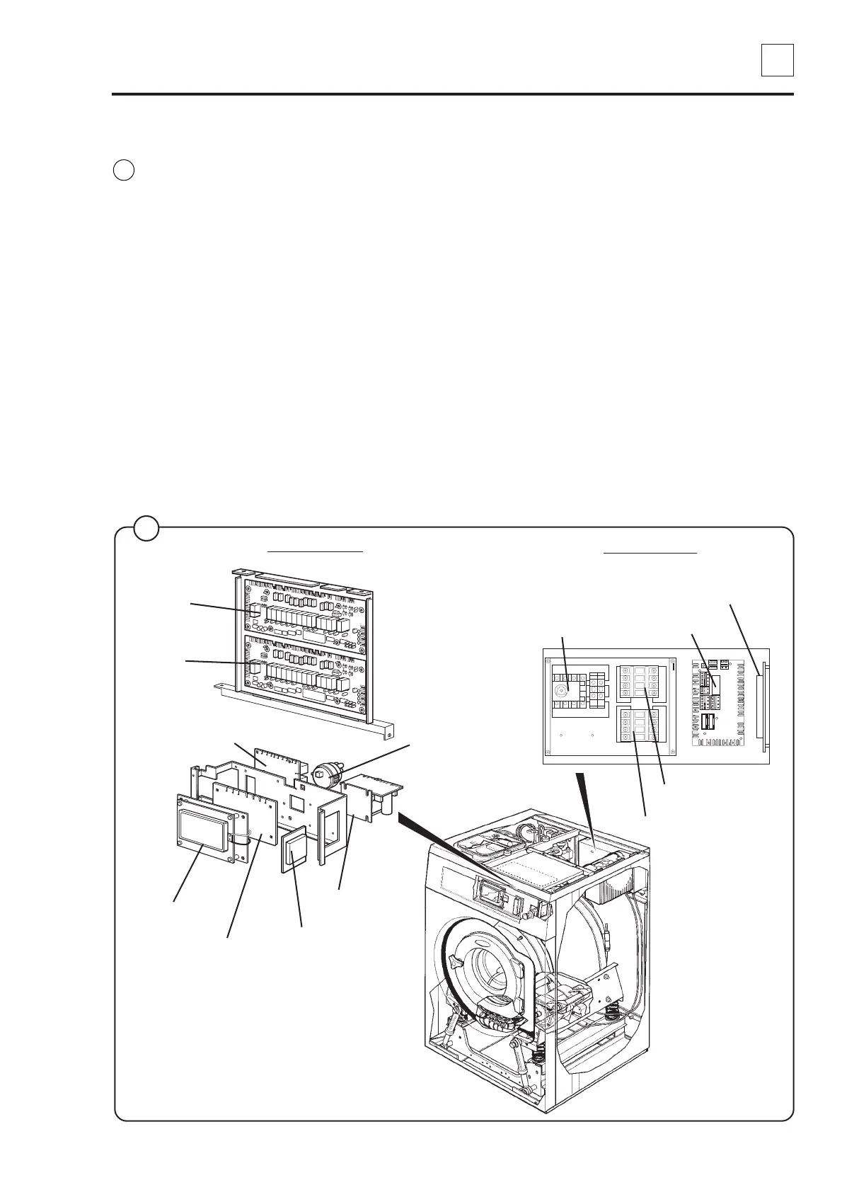
21. Control unit
21
3
438 9145-21/03
02.38
Service
Manual
Description
The control unit of the machine consists of the following parts:
• Front control unit
This unit contains two microcomputer controlled electronic
programme units consisting of a CPU card A1, display card A2,
card reader A3 and one or two I/O cards A11 and A12. The front
control unit also holds a door lock control A31 (double check of
door lock), a level guard B2 and a lower-voltage transformer T10
that supplies power to the programme unit.
• Rear control unit
This unit contains the main power switch Q1 or a connection block
with connectors for voltage supply, one or two heating contactors
K21 and K22 and one or two communication cards A21 and A22
with outputs for, among others, detergent supply.
Front control unit
Rear control unit
A1 CPU card
B2
Level guard
A31
Door lock control
T10
Transformer
Q1
Main power switch
K21 Heater contactor
A21
Communication card
K22 Heater contactor
(only larger machines)
5207 5227 5239
A2 Display Card
A11
I/O card 1
A12
I/O card 2
A3 Card reader
A22
Communication card
1
Fig.
1
 Loading...