21. Control unit
21
8
438 9145-21/03
02.38
Service
Manual
F12 F11
X71
S40
X81
Y11
Y12
Y13
Y14
Y24
Y22
Y15
Y25
X51
X50
X40
X41
X42
X43
X44
X45
X46
1
1
1
1
1
1
1
X72
X73
1
1
1
1
X70
X53
1
1
1
X47 X48
X49
X80
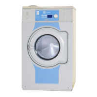
Communication card A21
This card is used to send and receive signals
from I/O card 1. It contains:
• Fuses F11 and F12 (T 1.25 A)
Protects the received voltage supply in the
timer and door lock controller.
• Service button S40
Used to engage service mode of the
programme unit.
• Input/output connection blocks
Card No. Function
Outputs (200 - 240 V AC)
X71 :1,2 Signal “Door locked, program on”
X72 :2 Liquid detergent 1
:3 Liquid detergent 2
:4 Liquid detergent 3
:5 Liquid detergent 4
:1 0 V
X73 :1 Powder 1 (Y11)
:2 Powder 2 (Y12)
:3 Powder 3 (Y13)
:4 Powder 4 (Y14)
:5 Powder 2 (Y22)
Input
X70 :1,2 Start/Stop
:3,4 Pause/PC5
Communication card A21
8
9
Fig.
8
5233
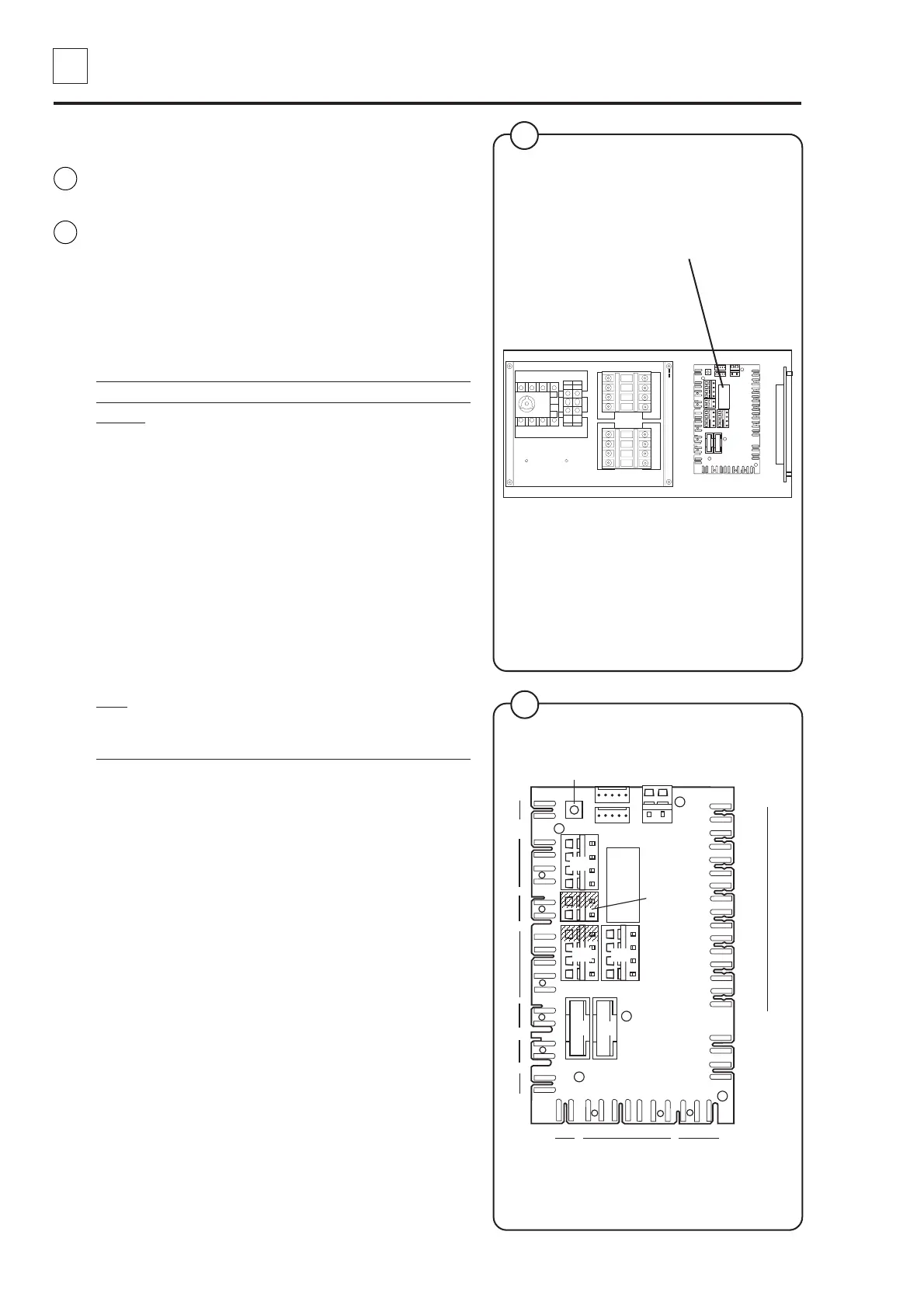
Pump
Drain
5239
Fig.
9
 Loading...