ECH 200 BD
22/76
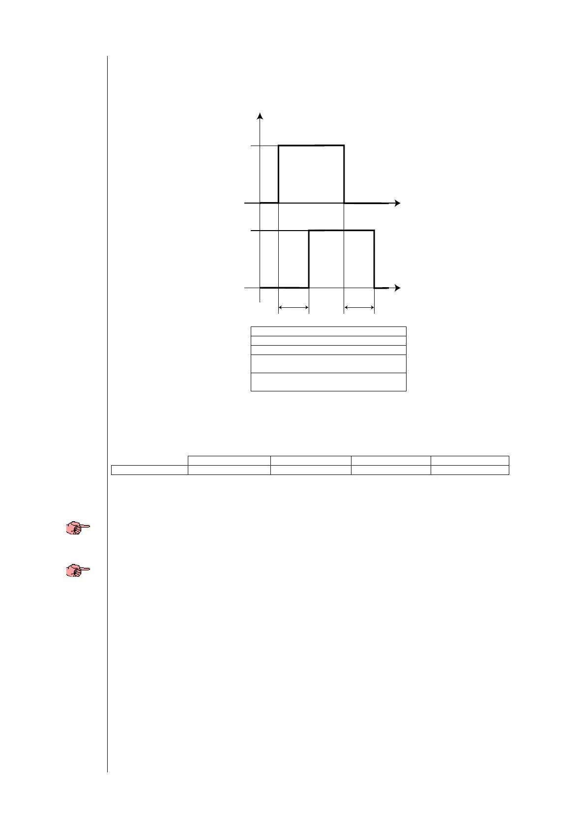
If the system includes 2 compressors (or capacity steps) there are intervals of time which must pass between turning on of
the 2 compressors (Pa C06) and turning off of the 2 compressors (Pa C07). An amount of time determined by parameter
Pa D11 (compressor on delay during defrosting) must pass between turning on a compressor and a capacity step.
The off time interval between compressors is not applied in the event of a compressor shutdown alarm, in which case
they stop immediately.
COMPR1: compressor 1
COMPR2: compressor 2
Time: time in seconds
Pa C05: on time interval between
compressors
Pa C07: off time interval between
compressors
6.2 Condensation fan
Various fan piloting modules can be connected to “Ech 200”, based on the models available
Look at the following table:
TK TC 4-20mA 0-10V
Ech 210 * *
Legend:
• TK: 230V~/2A command
• TC: control signal for fan control modules (500w,1500w,2200w)
• 4-20mA o 0-10V: standard command for fan control through external module (inverter).
• On model Ech 210 BD, the fan may be controlled with a proportionate output with a maximum load of 2A.
6.2.1 Fan configuration
The reference is to the fan control unit located outside near the heat exchanger which normally acts as a condenser. If a
heat pump is used, the exchanger will operate as an evaporator.
First of all, connect the fan up correctly to the appropriate output (refer to connection diagrams).
The fan output may be configured to work proportionately or as ON-OFF.
Pa F01 – Selection of triac output mode (TK and TC):
• 0= proportional fan output (TK)
• 1= ON-OFF fan output; in this mode the fan will be off if the proportional control has an output of 0 , on at
maximum speed (no capacity step) if control output is greater than 0.
• 2= external anti-freeze electrical heater control, for water-water machines with gas reversal
• 3= fan command for ON-OFF operation in response to compressor request. In this mode the fan is turned off
and on depending on compressor status.
The fan may also be controlled by the output associated with the optional board:
Pa H25 – configuration of optional board:
• 0= Open Collector output for second compressor
• 1= 4...20 mA fan speed output
• 2= 0-10 V fan speed output
If the output is configured as proportional TK the PICK-UP, PHASE SHIFT and IMPULSE DURATION parameters are also
significant.
Timing
On-on and off-off
diagram for 2
comp.
On-on and off-off
diagram for 2
comp.
Pa C07
Pa C05
ON
OFF
Time
COMPR2
ON
OFF
Time
COMPR1