ECH 200 BD
60/76ECH 200 BD
/76
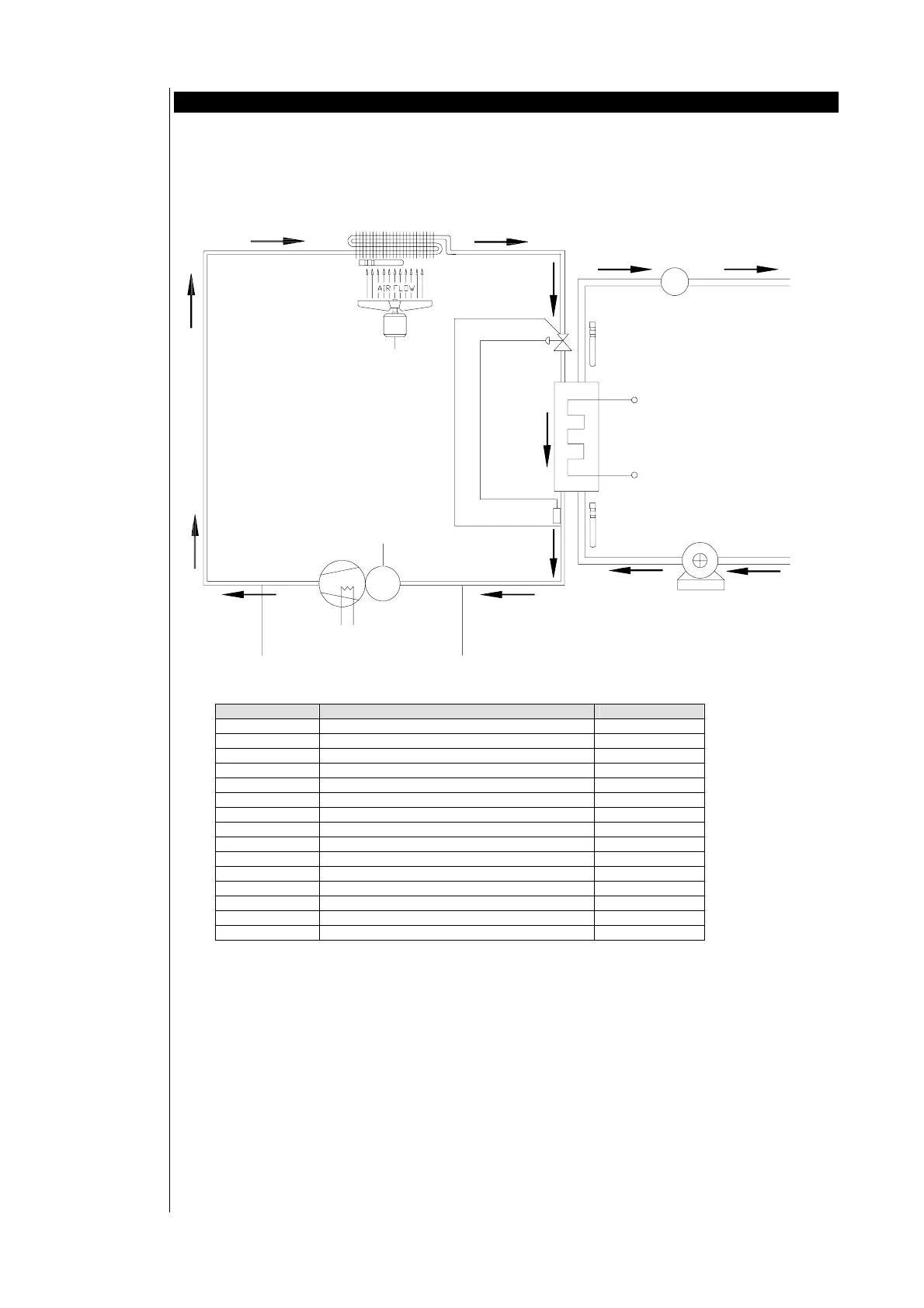
16 EXAMPLES OF AIR CONDITIONING CIRCUITS
The following chapter reports the main air-conditioning diagrams in their standard configuration.
Obviously the manufacturer can decide to set the system in customed way.
16.1 Air-water chiller 1 compressor
SYMBOL ELEMENT CONNECTION
COND condenser
EV evaporator
AFR a primary circuit anti-freeze resistance NO4
HPS a high pressure switch ID1
LPS a low pressure switch ID2
TS a fan thermal switch ID4
TS b compressor thermal switch ID3
ST a secondary circuit anti-freeze probe AI3
ST b primary circuit inflowing water probe AI1
ST c primary circuit outflowing water probe AI2
FS a primary circuit flow switch ID5
COMP a compressor NO1
WP a primary circuit water pump NO2
OCW outflowing cold water
IW inflowing water
WP a
AFR a
FS a
ST c
EV
ST a
TS a
COMP a
TS b
LPS aHPS a
COND
IW
OCW
ST b
TK