11 PARAMETERS
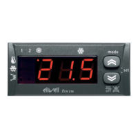
Parameters make the ”Ech 200” a fully configurable device.
They may be modified through:
• instrument keyboard
• copy card
• personal computer (with a suitable connection and “Param manager” software)
11.1 Description of parameters
We will now look at parameters in detail, divided by category.
11.1.1 Configuration parameters
Determine the features of the machine. If one or more parameters in this category are modified, the controller must be
switched off after the modification and switched on again to ensure correct operation.
Values marked with a (*) are valid only for Ech 2xxB
“Cooling” set point
Allows the set point to be set on “cooling” mode.
“Heating” set point
Allows the set point to be set on “heating” mode
Maximum set point during “heating”
Upper limit on set point in “heating” mode
Minimum set point during “heating”
Lower limit on set point in “heating” mode
Maximum set point during “cooling”
Upper limit on set point in “cooling” mode
Minimum set point during cooling
Lower limit on set point in “cooling” mode
AI1 Configuration
Used to configure analogue input Al1
• 0= No probe
• 1= Inlet water/air analogue input
• 2= Heating request digital input
• 3= Regulation algorithm request digital input
• 4= Differential NTC input
• 5= On remote keyboard (*)
AI2 Configuration
• 0= No probe
• 1= Outlet water/antifreeze/inlet air analogue input
• 2= Cooling request digital input
• 3= Anti-freeze alarm digital input
AI3 Configuration
• 0= No probe
• 1= Condensation control analogue input
• 2= 4...20 mA condensation input
• 3= 4...20 mA dynamic set point input
• 4= Antifreeze analogue input for water-water machines with gas reversal
• 5= Regulation algorithm input in “heating” mode for water-water machines with manual reversal
AI4 Configuration
• 0= No probe
• 1= Condensation control NTC input
• 2= Multifunctional digital input
• 3= Outdoor temperature NTC input
• 4= Antifreeze analogue input for water-water machines with gas reversal
Bottom of scale pressure value
Maximum inlet value; determines the value corresponding to a current of 20 mA
Polarity of digital input ID1
Polarity of digital input ID2
Polarity of digital input ID3
Polarity of digital input ID4
Polarity of digital input ID5
• 0= Active when contact closed
• 1= Active when contact open
Polarity of analogue input Al1
Polarity of analogue input Al2
Polarity of analogue input Al4
If configured as digital inputs:
• 0= Active when contact closed
• 1= Active when contact open
Configuration of digital input ID3
Configuration of digital input ID4
Configuration of digital input ID5
• 0= Compressor 1 thermal switch
• 1= Fan thermal switch
• 2= Flow switch
• 3= Remote Heat/Cool
• 4= Remote ON-OFF
Pa G01
Pa G02
Pa H01
Pa H02
Pa H03
Pa H04
Pa H05
Pa H06
Pa H07
Pa H08
Pa H09
Pa H10
Pa H11
Pa H12
Pa H13
Pa H14
Pa H15
Pa H16
Pa H17
Pa H18
Pa H19
Pa H20

 Loading...