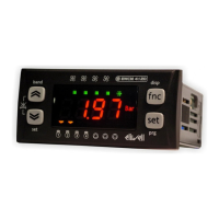
ECH 200 BD
48/76
• 2= 2 compressors (or 2 steps)
Enable pressure / temperature-based operation
• 0= parameters Pa H07=0 (probe Al3 absent) and Pa F01 = 3 (functioning in response to request from
compressor) are forced.
• 1= temperature-based operation; parameters Pa H07,Pa F01 are forced to: Pa H07= 1 (probe Al3 temperature),
Pa F01= 3 (functioning in response to request from compressor).
• 2= pressure-based operation; parameters Pa H07, Pa F01 are forced to: Pa H07= 2 (probe ST3 pressure), F01= 0
(proportional functioning).
• 3= no constraints are set on parameters
Compressor on sequence
• 0= compressors come on on the basis of number of hours of operation (balancing hours of operation)
• 1= compressor 1 is turned on first, followed by compressor (or capacity step) 2 (unvaried sequence).
Compressor 2 or capacity step polarity
• 0= relay ON if compressor 2/capacity step ON
• 1= relay ON if compressor 2/ capacity step OFF
selection of degrees °C or °F
• 0= degrees °C
• 1= degrees °F
SET display for air’/air macchine
In order to facilitate the user interface in the air/air version, the set associated with the selected mode is normally
displayed by setting th parameter PS H53
Customer Code 1
A number between 0 and 999 that the user can assign for internal use
Customer Code 2
A number between 0 and 999 that the user can assign for internal use
Polarity of relay alarm
• 0 = output is active (closed contact) when an alarm is active and when the machine is switched off.
• 1 = in the same conditions, the contact is open
Enable relay alarm in off position
• 0 =
alarm output not enabled in OFF or standby
• 1 = alarm output enabled in OFF or standby
11.1.2 Compressor parameters (CP)
OFF-ON safety time
The minimum amount of time that must pass between turning off the compressor and turning it on again. Expressed in
tens of seconds.
ON-ON safety time
The minimum amount of time that must pass between turning the compressor on and turning it on again. Expressed in
tens of seconds.
Cooling regulation algorithm hysteresis
May be used to select intervention differential in cooling mode.
Heating regulation algorithm hysteresis
May be used to select intervention differential in heating mode.
Regulation algorithm step intervention differential
May be used to set a temperature differential in relation to the set point beyond which the second step is activated.
Compressor 1 - compressor 2 (step) on interval
May be used to set a delay between turning on of two steps.
Compressor 1 - compressor 2 (step) off interval
May be used to set a delay between turning off of two steps.
Enables the Adaptive function.
0=disabled function; 1=enabled function;
Set block in Cooling mode
Enables to configure a set point that disables the Adaptive function in Cooling mode.
Set block in Heating mode
Enables to configure a set point that disables the Adaptive function in Heating mode.
Offset constant
Constant value of Adaptive algorithm
Reset time for increases
Function proportional constant
Value used to multiply the difference between the minimum and actual running time.
11.1.3 Fan control parameters (FAN)
Fan output configuration
• 0: proportional condensation control TK output
• 1: ON-OFF TK output
• 2: anti-freeze electrical heater output for water-water machines with gas reversal
• 3: TK ON-OFF output on compressor
Fan pick-up time
Time for which fan runs at maximum speed after starting up. Expressed in seconds/10.
Fan phase shift
May be used to adapt output to various types of fans.
Impulse duration of triac on
May be used to vary the length of the impulse from the triac.
Functioning in response to compressor request
• 0: if compressor is off, fan is off
• 1: condensation control independent of compressor
Minimum speed during cooling
Pa H49
Pa H50
Pa H51
Pa H52
Pa H53
Pa H54
Pa H55
Pa H56
Pa H57
Pa C01
Pa C02
Pa C03
Pa C04
Pa C05
Pa C06
Pa C07
Pa C08
Pa C09
Pa C10
Pa C11
Pa C12
Pa C13
Pa F01
Pa F02
Pa F03
Pa F04
Pa F05
Pa F06