ECH 200 BD
8/76
4 INSTALLATION
Before proceeding with any operation, first make sure that you have connected up the power supply to the
device through an appropriate external current transformer. Always follow these rules when connecting boards to
one another and to the application:
• Never apply loads which exceed the limits set forth in these specifications to outputs;
• Always comply with connection diagrams when connecting up loads;
• To prevent electrical couplings, always wire low voltage loads separately from high voltage loads;
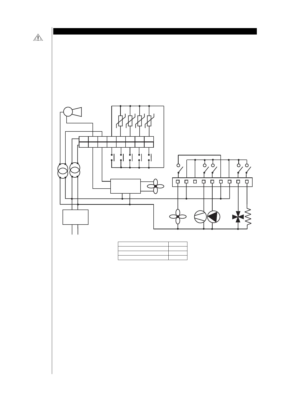
4.1 Connection diagrams
There are 2 ECH 200 BD models:
• ECH 210 BD: 2 step chiller + modbus
• ECH 215 BD: 2 step chiller + modbus
A: alarm output E: relay 1
B: LC filter F: relay 2
C: CF control G: relay 3
D: TK/relay 5 (only for 215B) H: relay 4
Connection to
probe AI3
configured as NTC
12AC AI1
ID1
GNDALL GND AI4 AI3 AI2
ID2
12DC TC ID5 ID4 ID3
C
B
Line
A
D E F G H
12AC