(((ELKRON))) - MP110
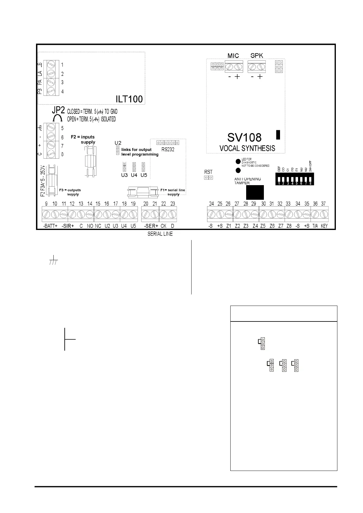
2.3 Terminal Board Description
1/2 LA/LB Telephone line input
3/4 PA/PB Telephone line output
5 Earth terminal for the
connection of the screen
6 - Negative of supply
7 + Positive of supply
8 C Battery test (Only PS515)
9 -BAT Battery negative
10 +BAT Battery positive
11 -SIR Negative of siren supply
12 +SIR Positive of siren supply
13 C
14 NO Relay output 1, max capacity 1 A 24Vdc
15 NC
16 U2 Open Collector electric output 2 (I max 10mA)
17 U3 Open Collector electric output 3 (I max 10mA)
18 U4 Open Collector electric output 4 (I max 10mA)
19 U5 Open Collector electric output 5 (I max 10mA)
20 -SER Devices supply on serial line
21 +SER Devices supply on serial line
22 CK Serial line (synchronism)
23 D Serial line (data)
24 -S Negative of detector supply
25 +S Positive of detector supply
26 Z1 Zone 1: programmable input
27 Z2 Zone 2: programmable input
28 Z3 Zone 3: programmable input
29 Z4 Zone 4: programmable input
30 Z5 Zone 5: programmable input
31 Z6 Zone 6: programmable input
32 Z7 Zone 7: programmable input
33 Z8 Zone 8: programmable input
34 -S Negative of detector supply
35 +S Positive of detector supply
36 TA 24h Input
37 KEY Mechanical key input
The type (NPN/PNP) of electrical
outputs U2,U3,U4,U5 can be
programmed through links.
Leaving the links as they are from the
factory (see figure above) electric
output is normally high (+12V) at rest
(PNP) and is lost in case of alarm. The
opposite setting makes output become
NPN,i.e. normally low (0V) at rest,
which is lost in case of alarm.
OUTPUT LEVEL
PROGRAMMING
10
F3-F1A-250V
F1-F1A-250V