SmartProg
Capability of ISP connector pins
Pin Description
1 VCCP for target device, with sense
2 H/L/read, GND
3, 10 H/L/read, VPP
4, 6, 8 H/L/read
5 NC
7,9 GND
Specification of ISP connector pins depends on the device,
which you want to program. You can find it in the control SW
for programmer (PG4UW), menu Device / Device Info
(Ctrl+F1). Be aware, the ISP programming way of respective
device must be selected. It is indicated by (ISP) suffix after
name of selected device.
These specifications correspond with application notes
published of device manufacturers. Used application notes you
may find on
www.elnec.com, section application notes.
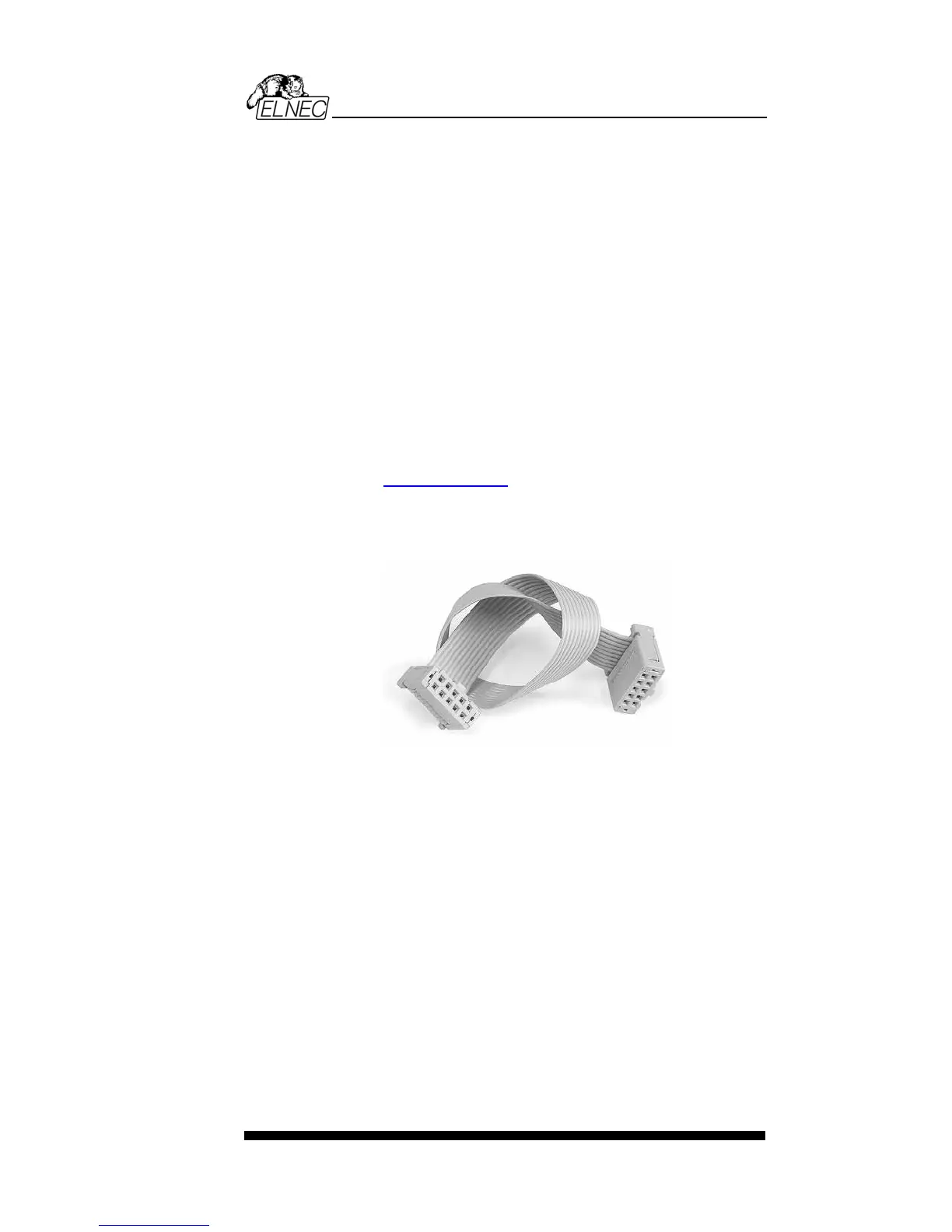
Note: Pin no. 1 is signed by triangle scratch on ISP cable
connectors.
SmartProg ISP cable
Warnings:
• When you use SmartProg as ISP programmer, don’t
insert device to ZIF socket.
• When you program devices in ZIF socket, don’t insert
ISP cable to ISP connector.
• Use only attached ISP cable. When you use other ISP
cable (other material, length…), programming may occur
unreliable.
• SmartProg can supply programmed device only, but
target system cannot supply SmartProg.
• SmartProg apply programming voltage to target device and
checks his value (target system can modify programming
voltage). If the programming voltage is different as
expected, no action with target device will be executed.
Note: H/L/read SmartProg driver
55