PIKprog+
Description of PIKprog+ ISP connector
1
2
3
4
5
6
7
8
9
10
Front view at ISP connector of programmer.
Capability of ISP connector pins
Pin Description
1 VCCP for target device, with sense
2 H/L/read, GND
3, 10 H/L/read, VPP
4, 6, 8 H/L/read
5 NC
7,9 GND
Specification of ISP connector pins depends on the device,
which you want to program. You can find it in the control SW
for programmer (PG4UW), menu Device / Device Info
(Ctrl+F1). Be aware, the ISP programming way of respective
device must be selected. It is indicated by (ISP) suffix after
name of selected device.
These specifications correspond with Microchip application
note: In-Circuit Serial Programming™(ICSP™) Guide. Used
application note you may find on
www.elnec.com, section
application notes.
Note: Pin no. 1 is signed by triangle scratch on ISP cable
connectors.
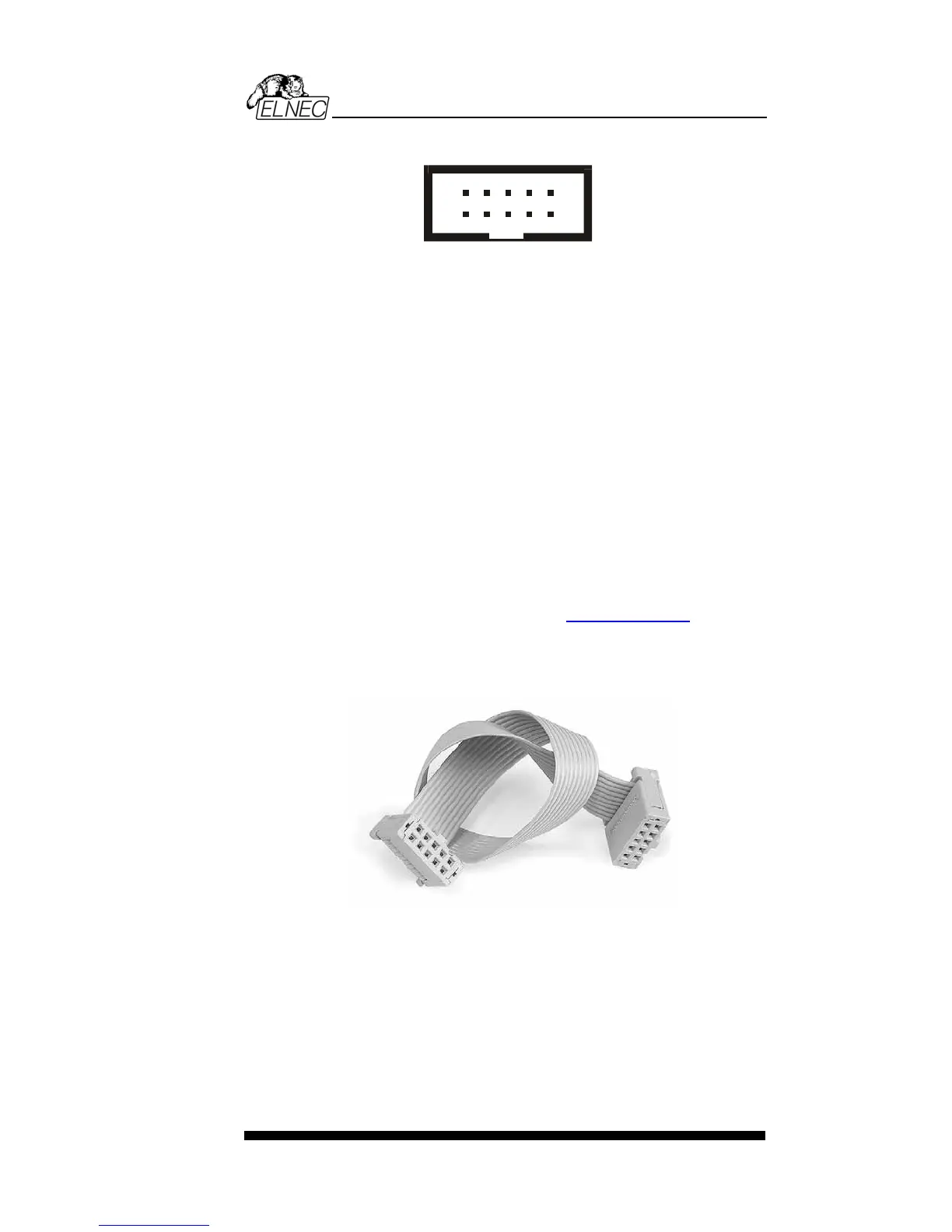
ISP cable of PIKprog+
Warnings:
• When you use PIKprog+ as ISP programmer, don’t insert
device to ZIF socket.
• When you program devices in ZIF socket, don’t insert
ISP cable to ISP connector.
• Use only attached ISP cable. When you use other ISP
cable (other material, length…), programming may occur
unreliable.
95