UFM Series 6
Q.Sonic-plus
Operation and Maintenance
If the Q.Sonic
plus
meter has to be in accordance with MID, extra restrictions
should be taken into account. Please see Chapter 12.4 Calibration (p.64).
4 Theory of Operation
An ultrasonic flow meter is an inferential measurement device that consists
of ultrasonic transducers that are typically located along a pipe's wall. The
transducers are inserted into the piping using a gas tight mechanism.
Ultrasonic pulses are alternately transmitted by one transducer and received
by the other one.
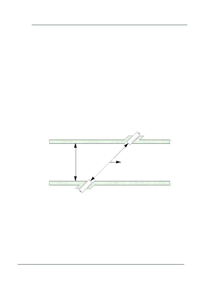
Figure 4-1 shows a simple geometry of two transducers, ‘A’ and ‘B’, at a
sharp angle “” with respect to the axis of a straight cylindrical pipe with
diameter “D”. Please note: the Q.Sonic
plus
flow meter employs reflection
paths, where the acoustic pulses reflect one or more times off the pipe wall.
Figure 4-1: Ultrasonic Measuring Line
4.1 Flow Velocity Measurement
The acoustic pulses are crossing the pipe like a ferryman crossing a river.
Without flow, they propagate with the same speed in both directions. If the
gas in the pipe has a flow velocity different from zero, pulses travelling
downstream with the flow will move faster, while those travelling upstream
against the flow will move slower. Thus, the downstream travel times “t
ab
“ will