17 VoIP Subscriber Gateways
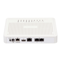
The following connectors and controls are located on the back panel (Table 4).
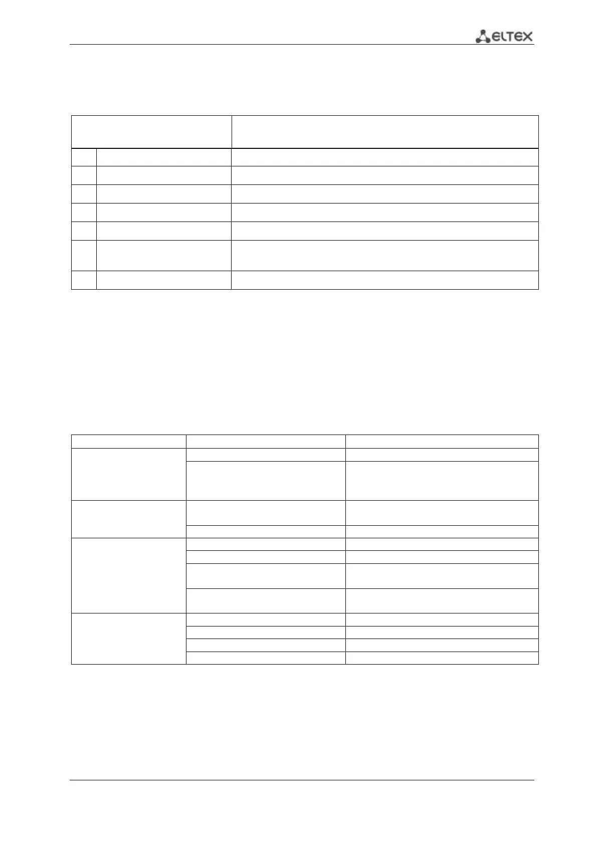
Table 4 – Description of the connectors and controls on the back panel
Connector for Wi-Fi-antennas connection
5
USB connector for external memory connection
8×RJ-11 connectors for analogue phone connection
10/100BASE-T port, 100BASE-TX (RJ-45 connector) for connection
to external network (WAN)
a functional key to reboot the device and reset it to factory settings
1.7 Light indication
Wi-Fi, WAN, Phone and Power LEDs display current state of the device located on the front
panel.
Status list of indicators is shown in Table 5 and 6.
Table 5 – Light indication of the device
transmitting data via Wi-Fi
solid green (10 Mbps)or orange (100
Mbps)
connection between station terminal and
subscriber device is established
packet data transmission via WAN interface
phone is on-hook, normal operation
flashes during with 20 Hz frequency
for 1 second, then 4 seconds pause
incoming call is on the phone port
green, flashes slowly in periods
subscriber port registration is absent at SIP-
proxy server
power is on, normal operation
reset the device to the factory settings
internet is not accessible
_______________________________________
For TAU-8.IP-W only
For TAU-8.IP-W only
 Loading...