6.3.4 Mounting and stacking exhaust modules, shutoff modules,
throttle modules, and single-channel pressure regulators
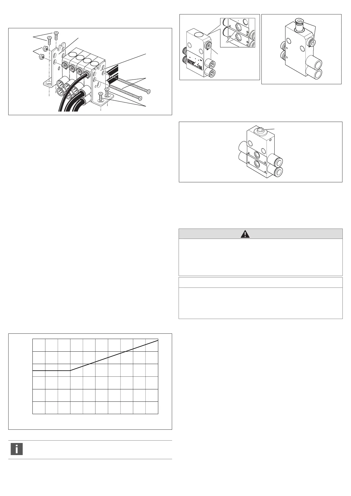
Fig.7: Mounting and stacking exhaust modules, shutoff modules, throttle mod-
ules, and single-channel pressure regulators
1 Nut M6 (not in scope of delivery) 2 Countersunk screw M4 (not in scope
of delivery)
3 Mounting bracket 4 Screw M6 (not in scope of delivery)
To stack the exhaust modules, shutoff modules, and throttle modules you will
need two M6 screws with nuts. The screws are used as tie rods. The length of the
screws depends on the number of function modules.
1. Align the function modules parallel to each other. Position the mounting
brackets (3) on the outside of the function modules.
2. Guide both M6 screws (4) through the two through holes on the mounting
brackets and function modules.
3. Place one M6 nut (1) on each of the two screws and tighten them.
Tightening torque: 1.2 ±0.2Nm
4. Fix the two mounting brackets on the mounting surface with two M4 counter-
sunk screws (2) each.
6.3.5 Connecting exhaust modules, shutoff modules, throttle
modules, and single-channel pressure regulators
1. Connect both operating lines to connections2 and 4.
2. Exhaust module: Connect the pilot air to the pilot control connection.
7 Operation
7.1 Exhaust module: Exhausting the operating line
7.1.1 Pneumatically operated exhaust module
u Apply at least the minimum pressure P2, which corresponds with the pressure
on connections 2 or 4, to the pilot control connection to actuate the exhaust
module.
Fig.8: Minimum control pressure depending on operating pressure
The exhaust module and the air circuit should be tested monthly to en-
sure they function correctly.
Fig.9: Exhaust module
Fig.10: Exhaust module with 2x ex-
haust
10 Connection for the pilot air line 11 Exhaust
7.1.2 Mechanically operated exhaust module
Fig.11: Mechanically operated shutoff module
29 Manual actuation
u Press the actuating control (29) to exhaust the operating lines.
7.2 Pressure regulator: Setting the working pressure
CAUTION
Danger of injury due to escaping compressed air!
The pressure gauge connections are pressurized and must therefore always be
closed off with a pressure gauge or blanking plugs during operation.
u Only remove the pressure gauge or blanking plugs when no compressed air
is applied to the working connection.
NOTICE
Danger of overturning the adjustment screw!
Damage to the pressure regulator!
u Never turn the adjustment screw firmly all the way to the stop (maximum
tightening torque: 1Nm).
The appropriate AV valve must be controlled so that you can set the working
pressure.
For single-channel pressure regulators, you can control the pressure either at
connection2 or connection4, depending on the version.
For two-channel pressure regulators, you can control the pressure at connec-
tion2 and at connection4 independent of each other.
To set the pressure in the operating line you must adjust the adjustment screws
for connections2 or 4. The pressure in the operating line can be checked by
mounting a pressure gauge to the respective pressure gauge connections (12,
13).
1. Replace the blanking plugs (14) with a pressure gauge (Ø 4) (15).
2. Release the lock nut (16) on the adjustment screw (17, 18).
3. Turn the adjustment screw in a clockwise direction to increase the pressure.
The setting in the end stop corresponds with the unregulated working pres-
sure.
Turn the adjustment screw in an anti-clockwise direction to reduce the pres-
sure.
4. Retighten the lock nut once the required pressure has been set.
AVENTICS™ | R422003121-BAL-001-AE | English 16