10. Attach the Backplane to the enclosure standoffs with the four Phillips head screws. If
the Local Display Module is installed on the Backplane, use a flat blade screw driver
and install the four flat-head screws into the enclosure standoffs.
11. Reinstall the J7 terminal block, if removed, on the Backplane board. Re-install the
CPU Module, Optional I/O Module (if installed) and the Power Supply.
12. Recheck the connections, wiring and switch settings before replacing the end caps.
13. If replacing other electronics, continue with the following procedures before
replacing the end caps and sealing the enclosure.
14. If you are not replacing other electronics, replace the end caps and security latches
(3 mm Allen wrench required). If required, install the security seal wire into and
through one of the two holes in the end cap. Choose holes that minimize
counterclockwise rotation of the end cap when the security wire is taut (maximum
wire diameter .078 inch; 2.0 mm).
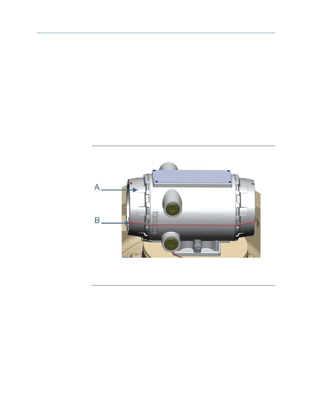
Transmitter electronic enclosure security sealsFigure 3-22:
A. Transmitter Electronics Enclosure end cap
B. Security wire seals
15. Adjust the security wire, removing all slack and thread into the lead seal.
16. Cut wire ends to remove excess wire.
17. Apply power to the meter.
18. This completes the I.S. Barrier Board replacement procedure.
19. If you encounter problems with this procedure, see the Lifecycle Customer Service
contact information on the back cover of this manual.
Replace the Power Supply Board
1. If replacing the Power Supply board remove power to the meter.
Meter repairs
Maintenance and Troubleshooting manual 77

 Loading...


