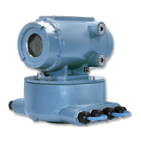
2. Disconnect the Transmitter Electronics Enclosure security seals, loosen the end cap
security latches with a 3mm Allen wrench and remove both end caps (see
Figure 3-19).
3. Use a flat head screw driver and remove the terminal blocks from the Power Supply
board, the CPU Module and the Optional I/O Module (if installed). See Figure 3-17 for
board locations and associated terminal blocks.
4. Use a Phillips head screw driver and remove the four Backplane board screws from
the enclosure standoffs. If the Local Display Module is installed on the Backplane,
use a flat blade screw driver and install the four flat-head screws into the enclosure
standoffs.
Meter repairs
78 Gas Ultrasonic Flow Meters

 Loading...


