EasyManua.ls Logo

Emerson EV2000 Series - User Manual

Emerson EV2000 Series
131 pages
To Next Page IconTo Next Page
Loading...
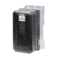
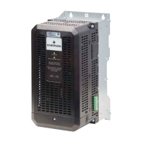
EV2000 Series Universal Variable Speed Drive
User Manual
Version V3.2
Revision date August 11, 2008
BOM 31011126
Emerson Network Power provides customers with technical support. Users may
contact the nearest Emerson local sales office or service center.
Copyright © 2005 by Emerson Network Power Co., Ltd.
All rights reserved. The contents in this document are subject to change without
notice.
Emerson Network Power Co., Ltd.
Address: No.1 Kefa Rd., Science & Industry Park, Nanshan District 518057,
Shenzhen China
Homepage: www.emersonnetworkpower.com.cn
Customer Service Hotline: +86 755 86010581
Complaint Hotline: +86 755 86010800
E-mail: support@emersonnetwork.com.cn

Table of Contents

Questions and Answers:

Emerson EV2000 Series Specifications

General IconGeneral
Operating Temperature0°C to 40°C (32°F to 104°F)
Output Voltage0 to Input Voltage
Power RatingUp to 1500 kW
Communication InterfaceEthernet
Protection FeaturesOvercurrent, Overvoltage, Undervoltage, Overtemperature, Short Circuit
Input Voltage200-240V AC, 380-480V AC

Summary

Preface

Unpacking Inspection

Checks after receiving the drive.

Model designation rules

Explanation of product model naming.

Chapter 1 Safety

1.1 Safety

General safety warnings and precautions for operation.

1.2 Notes for Installations

Safety guidelines for drive installation.

1.3 Notes for Using EV2000

Important considerations for using the drive.

1.3.1 About Motor and Load

How the drive interacts with motors and loads.

1.3.2 About Variable Speed Drive

Specific operational points for the drive.

1.4 Disposing Unwanted Drive

Proper disposal instructions for the drive.

Chapter 2 Product Introduction

2.1 Specifications

Technical details and ratings of the drive.

2.2 Product Series

Details on different drive models and their specifications.

2.3 Optional Parts

Information on available accessories for the drive.

Chapter 3 Installation and Wiring

3.1 Installation Environment

Requirements for drive installation location and space.

3.2 Removing and Mounting of Parts

Procedures for handling drive components.

3.3 Wire Connections of Drive

Detailed instructions for electrical wiring.

Chapter 4 Operation Instructions

4.1 Notice

Key terms and concepts for understanding drive operation.

4.2 Operating Instructions

Step-by-step guides for operating the drive.

4.3 Start-up

Procedures for initial drive startup.

Chapter 5 Parameter Introductions

5.1 Basic Operating Parameters(Group F0)

Core parameters for fundamental drive operation.

5.2 Parameters of Reference Frequency (Group F1)

Parameters for setting the desired operating frequency.

5.3 Starting and Braking Parameters (Group F2)

Parameters controlling acceleration, deceleration, and braking.

5.8 Function of Terminals(Group F7)

Configuration of multi-function input/output terminals.

5.13 Motor Parameters (Group FH)

Parameters related to the connected motor.

5.14 Protective Function (Group FL)

Overload and other protection settings.

5.12 Communication Parameters (Group FF)

Settings for serial communication.

Chapter 6 Troubleshooting

Table 6-1 Faults and actions

List of common faults and their remedies.

Table 6-2 Abnormal phenomena and handling methods

Troubleshooting common operational issues.

Chapter 7 Maintenance

7.1 Daily Maintenance

Routine checks for daily operation.

7.2 Periodical Maintenance

Recommended maintenance schedule.

7.3 Replacing Wearing Parts

Procedures for replacing worn components.

Appendix 1 Parameters

Group F0: Basic Operating Parameters

Core parameters for fundamental operation.

Group F2: Starting and Braking Parameters

Parameters for motor start/stop and braking.

Group F7: Terminal Function Parameters

Configuration of I/O terminals.

Group FH: Motor Parameters

Motor specific parameters.

Group FL: Protection Parameters

Drive and motor protection settings.

Group FF: Communication Parameters

Serial communication settings.

Appendix 2 Accessories

AC;DC Reactor

Details and specifications for AC/DC reactors.

380 V Series EMI Filter

Sizes and parameters for EMI filters.

Appendix 3 Communication Protocol

1 Networking Mode

Different network configurations for drives.

4 Protocol Format

Structure of communication commands and data frames.

5.3 Response of Slave to Master’s Command

How the drive responds to master commands.

5.4 Index Section

Meaning of index bytes in communication.

Related product manuals