Parameter
structure
Keypad and
format
Advanced
parameter
descriptions
Serial comms
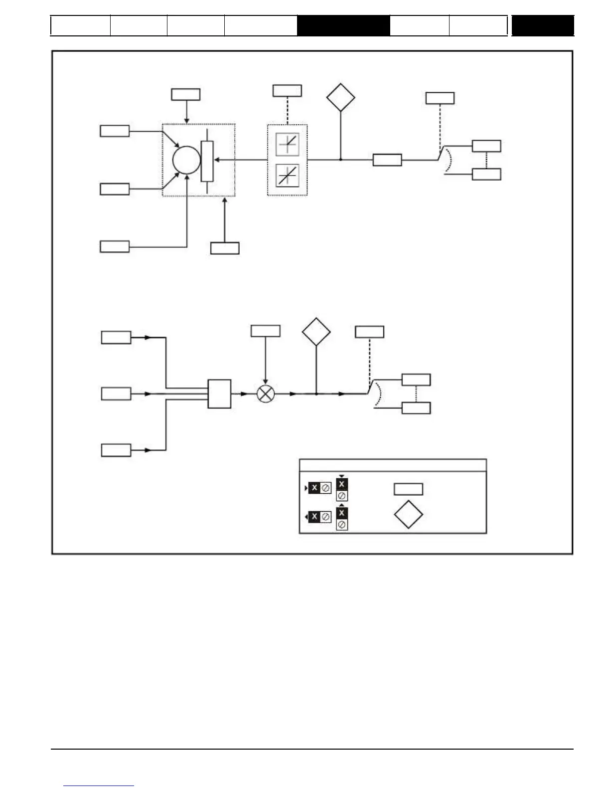
Figure
5-28
Menu
9
logic
diagram:
Motorized
pot
and
binary
sum
Motorized
pot. rate
9.23
Motorized
pot. bipolar
select
9.22
Motorized pot.
output indicator
9.03
Motorized pot.
destination
parameter
9.25
Motorized pot.
up
9.26
Any
unprotected
variable
parameter
??.??
M
9.24
Motorized pot.
output scale
??.??
9.27
Motorized pot.
down
Function disabled if set
to a non valid destination
9.28
Motorized pot.
reset to zero
9.21
Motorized pot.
mode
Binary-sum
offset
Binary-sum
logic output
value
Binary-sum
logic destination
parameter
9.29
9.34
9.32
9.33
Any
Binary-sum
logic ones (LSB)
9.30
Binary-sum
logic twos
9.31
Binary-sum
+
+
unprotected
bit
parameter
??.??
??.??
Function disabled if set
to a non valid destination
Key
logic fours (MSB)
Input
terminals
Output
terminals
0.XX
0.XX
Read-write (RW)
parameter
Read-only (RO)
parameter
The parameters are all shown at their default settings
Menu 9 contains two logic block functions (which can be used to produce any type of two input logic gate, with or without a delay), a motorized pot
function and a binary sum block. One menu 9 or one menu 12 function is executed every 4 ms. Therefore the sample time of these functions is 4 ms
x number of menu 9 and 12 functions active. The logic functions are active if one or both the sources are routed to a valid parameter. The other
functions are active if the output destination is routed to a valid unprotected parameter.
Mentor MP Advanced User Guide
123
Issue Number: 4
www.onxcontrol.com

 Loading...

