Parameter
structure
Keypad and
format
Advanced
parameter
descriptions
Serial comms
Example
of
uncoiler
operation:
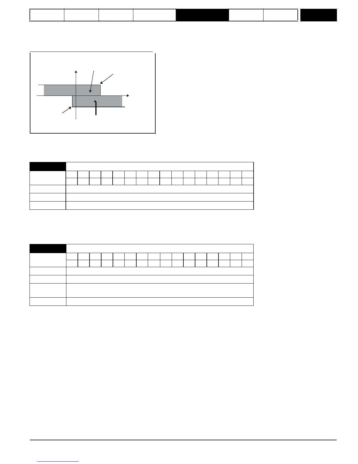
This is an example for an uncoiler operating in the positive direction. The final speed demand should be set to a level just above the maximum normal
speed. When the resultant torque demand is negative the uncoiler will apply tension and try and rotate at 5 rpm in reverse, and so take up any slack.
The uncoiler can operate at any positive speed applying tension. If it is necessary to accelerate the uncoiler a positive resultant torque demand is
used. The speed will be limited to the final speed demand. The operating area is the same as that for the coiler and is shown below:
Area for accelerating
uncoiler: positive torque,
limited speed
Torque
Speed reference
Speed
-5rpm
Area for normal uncoiler
operation: negative torque,
limited to low speed in reverse
4:
Speed
control
with
torque
feed-forward
The drive operates under speed control, but a torque value may be added to the output of the speed controller. This can be used to improve the
regulation of systems where the speed loop gains need to be low for stability.
of position feedback quantization noise. The filter introduces a lag in the speed loop, and so the speed loop gains may need to be reduced to maintain
stability as the filter is increased. Alternative filters can be selected depending on the value of the speed controller gain selector (Pr
3.16
). If Pr
3.16
=
0 Pr
4.12
is used, if Pr
3.16
= 1 Pr
4.23
is used.
auto-tuning feature (see Pr
5.12
{
SE13,
0.34
}).
It is possible to increase the proportional gain (Kp) to reduce the response time of the current controllers. If Kp is increased by a factor of 1.5 then the
response to a step change of reference will give 12.5 % overshoot. It is recommended that Ki be increased in preference to Kp.
The gain values that are calculated by the autotune system should give the best response with minimal overshoot. If required the gains can be
adjusted to improve performance.
Pr
4.13
= 3393 x L x f x Imax / V rms
Where :
L is the load inductance in Henries
R is the load resistance in ohms
f is the supply frequency in Hertz
Imax is the peak load current (including any overload) in amps
V rms is the line-to-line supply voltage in volts.
Mentor MP Advanced User Guide
63
Issue Number: 4
www.onxcontrol.com
4.13

 Loading...

