Parameter
structure
Keypad and
format
Advanced
parameter
descriptions
Serial comms
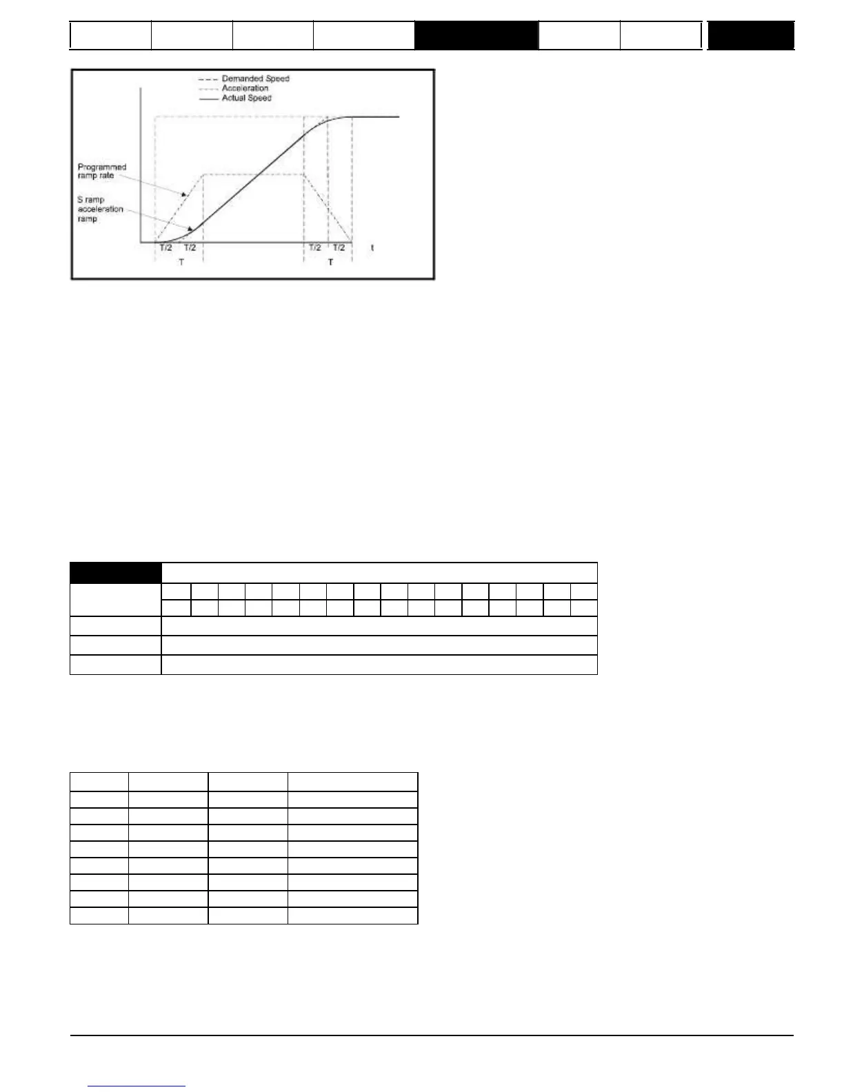
The time taken in seconds for the ramp output to change by speed (⊗w*) is given below. Two cases are given because the total ramp time must be
calculated with a different equation depending on whether the acceleration is able to reach the selected ramp rate (A1) or not. If the required change
is small the selected ramp rate is not reached and the ramp does not include the central linear ramp region. If the required change is larger the ramp
does include the central linear region as shown in the diagram above.
Speed
⊗w*
linear
=
1000
x
J
/
A1
2
where:
A = selected ramp rate
J = Pr
2.07
If
the
required
change
is
less
than
⊗w*
linear
then
T
Ramp1
should
be
used,
but
if
the
speed
change
is
greater
or
equal
to
⊗w*
linear
T
Ramp2
should
be
used.
T
Ramp1
=
2
(⊗w*
x
Pr
2.07
/
1000)
T
Ramp2
=
(⊗w*
x
A
/
1000)
+
(Pr
2.07
/
A)
The default values for the ramp rate and S ramp acceleration limit have been chosen such that for the default maximum speed, the curved parts of
the S ramp are 25 % of the original ramp if S ramp is enabled. Therefore the ramp time is increased by a factor of 1.5.
0
Ramp rate selection by terminal input
1-8
Ramp rate defined by parameter number, i.e. 1 = Pr
2.11
{
SE03,
0.24
}, 2 = Pr
2.12
, etc.
9
Ramp rate selection by Pr
1.50
When Pr
2.10
is set to 0 the acceleration ramp rate selected depends on the state of bit Pr
2.32
to Pr
2.34
. These bits are for control by digital inputs
be programmed to operate with each reference. Since the new ramp rate is selected with the new reference, the acceleration applies towards the
selected preset if the motor needs to accelerate to reach the preset.
Mentor MP Advanced User Guide
37
Issue Number: 4
www.onxcontrol.com
2.10

 Loading...

