Parameter
structure
Keypad and
format
Advanced
parameter
descriptions
Serial comms
The sample time for this function is 4 ms x number of menu 9 and 12 functions active. Extending the sample time does not cause any overflow errors
within the function however, care must be taken to ensure that the input or output positions do not change by more than half a revolution within the
sample time, i.e for a sample time of 4 ms the input or output speed should not exceed 7500 rpm, for a sample time of 8 ms the speed should not
exceed 3750 rpm, etc. If the output of this function is to supply a reference to the position controller in menu 13 it must be the only user function in
menu 9 or 12 enabled.
If
another
function
is
enabled
the
input
to
the
position
controller
will
only
change
every
8
ms
(i.e.
every
2
samples
of
the
position
controller)
and
the
speed
reference
applied
to
the
drive
could
be
very
noisy.
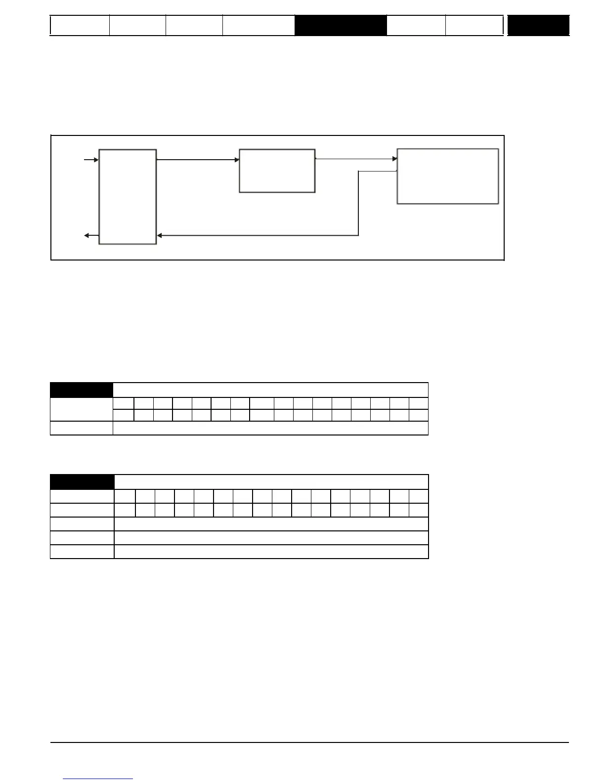
The following diagram shows how the variable selector in Sectional control mode can be used to provide a position reference for the drive and act as
a source for encoder simulation to give the position reference for the next drive in the system.
Input
reference
SM-Universal
Encoder Plus
module
Source
Pr
12.08
=Pr
x.05
Variable selector
in sectional control
mode
Destination
Pr
12.11
= Pr
13.21
Menu 13 position controller
Reference source
Pr
13.04
=Local(4)
Ignore local reference turns
Pr
13.24
=1
Output
reference
Encoder simulation source
Pr
x.24
= Pr
13.21
The input reference is provided by the previous drive in the system via the SM-Universal Encoder Plus module and is used as the position source
(Pr
12.08
) for the variable selector. The destination of the variable selector is the local position reference for the menu 13 position controller
(Pr
13.21
). Pr
13.21
counts up or down based on the delta position from the variable selector and rolls over or under at 65535 or 0. If the controller is
set up to ignore the local reference turns then Pr
13.21
can be used as the position controller reference.
If Pr
13.21
is also used as the encoder simulation source the local reference can also be used to give the reference for the next drive in the system.
With this arrangement a ratio is provided between the input reference and output reference within the variable selector. An addition ratio can be
provided within the position controller between the position in Pr
13.21
and the position reference used by the position controller. The variable
selector speed reference can be used to move the position reference forwards or backwards with respect to the input reference.
5.13.3
Brake
control
function
zero to apply the brake. Digital I/O can be automatically configured to use this parameter as a source (see Pr
12.41
).
The brake controller is disabled and no other drive parameters are affected by the brake controller. When this parameter is changed from a non-zero
value to zero the following parameters are set to zero: Pr
2.03
, Pr
6.08
, Pr
13.04
and Pr
13.10
(if Pr
12.49
= 1).
1
=
rel
The brake controller is enabled with I/O set up to control the brake via the relay output T51/T52. Drive OK is re-routed to digital I/O 2 (T25).
2
=
d
IO
The brake controller is enabled with I/O set up to control the brake via digital I/O 2 (T25).
3
=
User
The brake controller is enabled, but no parameters are set to select the brake output.
The following tables show the automatic parameter changes that occur to set up digital I/O2 (T25) and the relay output (T51/52) after drive reset when
Pr
12.41
has been changed. The changes are done in two stages: the first stage restores the I/O used as defined by the initial setting of Pr
12.41
and
the second stage sets up the I/O as defined by the new setting of Pr
12.41
.
Mentor MP Advanced User Guide
165
Issue Number: 4
www.onxcontrol.com
12.41

 Loading...

