structure
Keypad and
format
Advanced
parameter
descriptions
Serial comms
31
16
15
0
Revolutions
Position
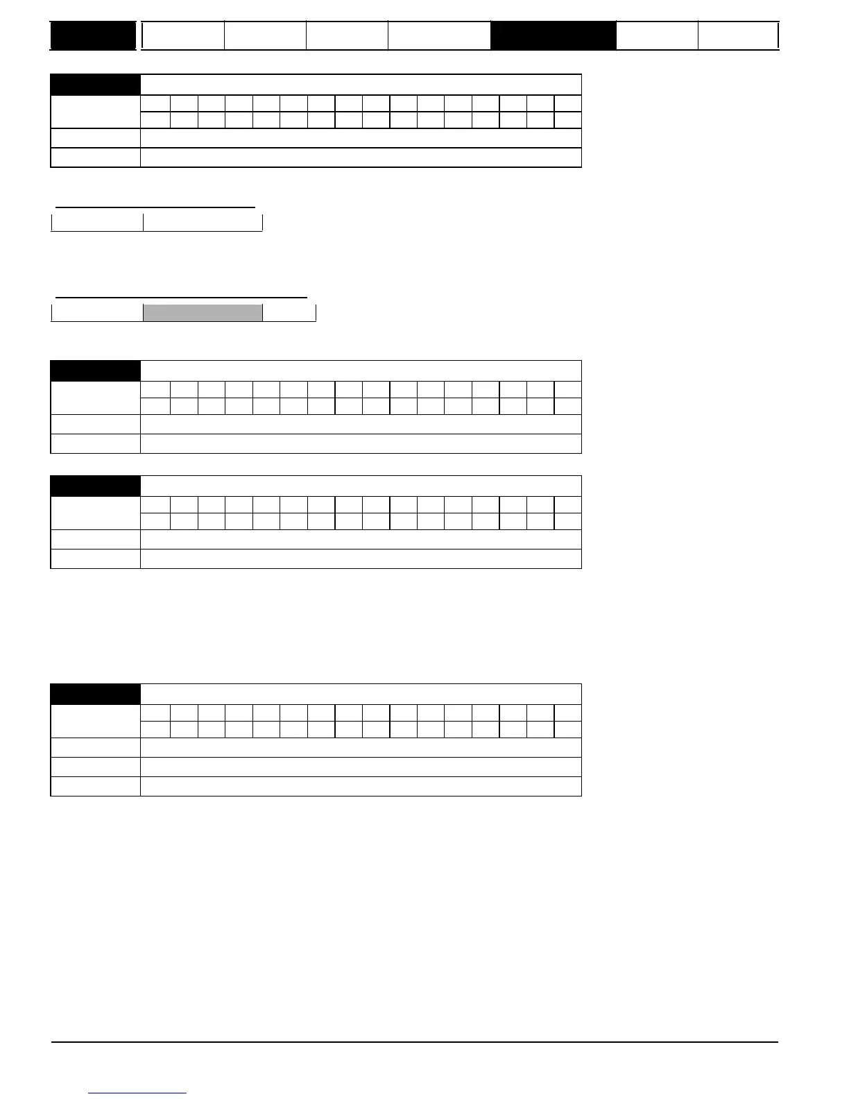
Provided the encoder setup parameters are correct, the position is always converted to units of 1/2
16
ths of a revolution, but some parts of the value
may not be relevant depending on the resolution of the feedback device. For example a 1024 line digital encoder produces 4096 counts per
revolution, and so the position is represented by the bits in the shaded area only.
31
16
15
4
3
0
Revolutions
Position
When the encoder rotates by more than one revolution, the revolutions in Pr
3.28
increment or decrement in the form of a sixteen bit roll-over counter.
the marker flag (Pr
3.31
= 0), or just to set the marker flag (Pr
3.31
= 1). The marker flag is set each time the marker input becomes active, but it is not
reset by the drive, and so it must be cleared by the user.
If Pr
3.35
is set to zero the marker system operates in a conventional manner and only resets the position (Pr
3.29
) and not the turns (Pr
3.28
) on a
marker event. If Pr
3.35
is set to one the whole position (Pr
3.28
and Pr
3.29
) are reset on a marker event. The full reset mode allows the marker to
give a form of registration where the marker event defines zero position.
It is sometimes desirable to mask off the most significant bits of the revolution counter of encoders. This does not have to be done for the drive to
function correctly.
If Pr
3.33
is zero the revolution counter (Pr
3.28
) is held at zero. If Pr
3.33
has any other value it defines the maximum number of
the revolution counter before it is reset to zero. For example, if Pr
3.33
= 5, then Pr
3.28
counts up to 31 before being reset.
50
Mentor MP Advanced User Guide
www.onxcontrol.com
Issue Number: 4
3.33

 Loading...

