format
Advanced
parameter
descriptions
Serial comms
2.7
Parameter
access
level
and
security
The parameter access levels determine whether the user has access to
Menu 0 (in sub block mode) only or to all of the advanced menus (Menus
1 to 23), in addition to Menu 0 (in linear mode).
The user security determines whether the access to the user is read only
or read write.
The user security and the parameter access level can operate
independently of each other as shown in Table 2-3 .
The default settings of the drive are parameter access level L1 and User
Security Open, i.e. read / write access to Menu 0 with the advanced
menus, not visible
2.7.1
User
security
The user security, when set, prevents write access to any of the
parameters (other than Pr
11.44
(
SE14,
0.35
) Access Level) in any
menu.
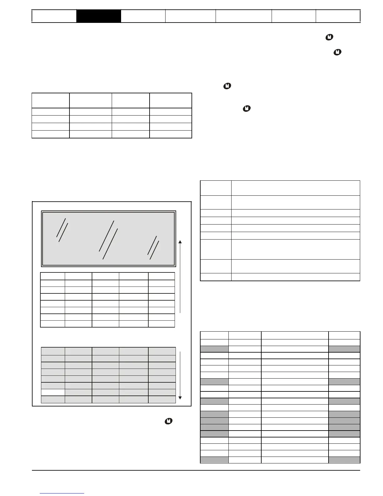
Figure
2-5
User
security
open
User
security
open
-
All parameters: Read / Write access
2.7.3
Unlocking
user
security
Select a read write parameter to be edited and press the
button; the
upper display will now show CodE.
Use the arrow buttons to set the security code and press the button.
With the correct security code entered, the display will revert to the
parameter selected in edit mode. If an incorrect security code is entered
the display will revert to parameter view mode.
To lock the user security again, set Pr
11.44
(
SE14,
0.35
) to Loc and
when one of the following conditions occur. If action is not taken to
eliminate the alarms except "Auto tune" and "PLC", the drive may
eventually trip. Alarms flash once every 640 ms except "PLC" which
flashes once every 10 s. Alarms are not displayed when a parameter is
shown on the 1st row and the trip string flashes on the 2nd row. The read
only parameters listed below are frozen with any trip except UV trip until
the trip is cleared. For a list of the possible trip strings see Pr
10.20
{
tr01,
0.51
}. Pressing any of the parameter keys changes the mode to the
parameter view mode. If the trip is HF01 to HF16 then no key action is
recognized.
User
security
closed
- All parameters: Read Only access
Enter a value between 1 and 999 in Pr
11.30
and press the
button;
the security code has now been set to this value. To activate the
security, the access level must be set to Loc in Pr
11.44
(
SE14,
0.35
).
When the drive is reset, the security code will have been activated and
the drive returns to access level L1. The value of Pr
11.30
will return to 0
in order to hide the security code. At this point, the only parameter that
can be changed by the user is the access level Pr
11.44
(
SE14,
0.35
).
Issue Number: 4
www.onxcontrol.com
 Loading...


