Cable sizing formula
M = 18V + (R x L x 0.7A)
• M: minimum supply voltage
• R: cable resistance
• L: cable length (in Ω/ft)
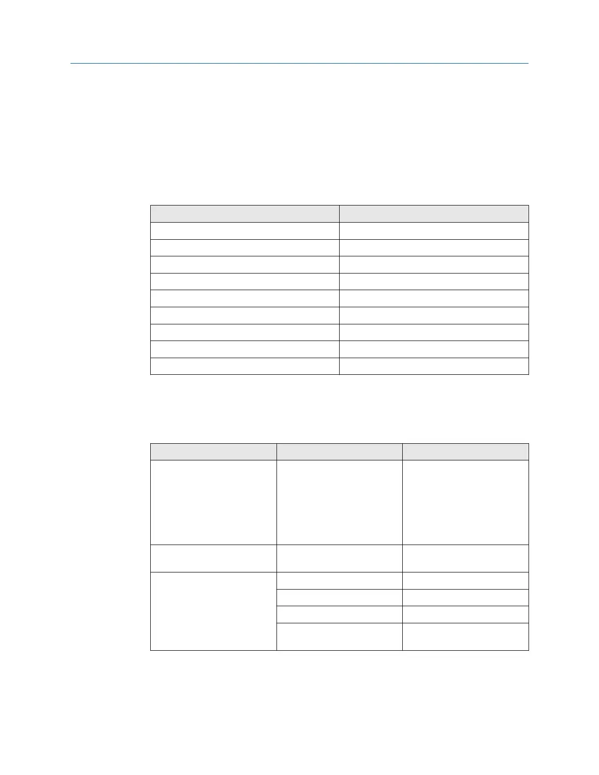
Typical power cable resistance at 68 °F (20.0 °C)
Wire gauge Resistance
14 AWG 0.0050 Ω/ft
16 AWG 0.0080 Ω/ft
18 AWG 0.0128 Ω/ft
20 AWG 0.0204 Ω/ft
2.5 mm
2
0.0136 Ω/m
1.5 mm
2
0.0228 Ω/m
1.0 mm
2
0.0340 Ω/m
0.75 mm
2
0.0460 Ω/m
0.50 mm
2
0.0680 Ω/m
2.3.1 Maximum cable lengths between sensor and transmitter
The maximum cable length between the sensor and transmitter, which are installed
separately, is determined by cable type.
Cable type
Wire gauge Maximum length
Micro Motion 4-wire remote
mount
Not applicable • 1,000 ft (305 m) without
Ex-approval
• 500 ft (152 m) with IIC
rated sensors
• 1,000 ft (305 m) with IIB
rated sensors
Micro Motion 9-wire remote
mount
Not applicable 60 ft (18 m)
User-supplied 4-wire VDC 22 AWG (0.326 mm²) 300 ft (91 m)
VDC 20 AWG (0.518 mm²) 500 ft (152 m)
VDC 18 AWG (0.823 mm²) 1,000 ft (305 m)
RS-485 22 AWG (0.326 mm²)
or larger
1,000 ft (305 m)
Planning Installation Manual
April 2022 MMI-20027478
10 Micro Motion 5700 Transmitters with Configurable Inputs and Outputs