3.6 Rotate the user interface on the transmitter
(optional)
The user interface on the transmitter electronics module can be rotated 90°, 180°, or 270°
from the original position.
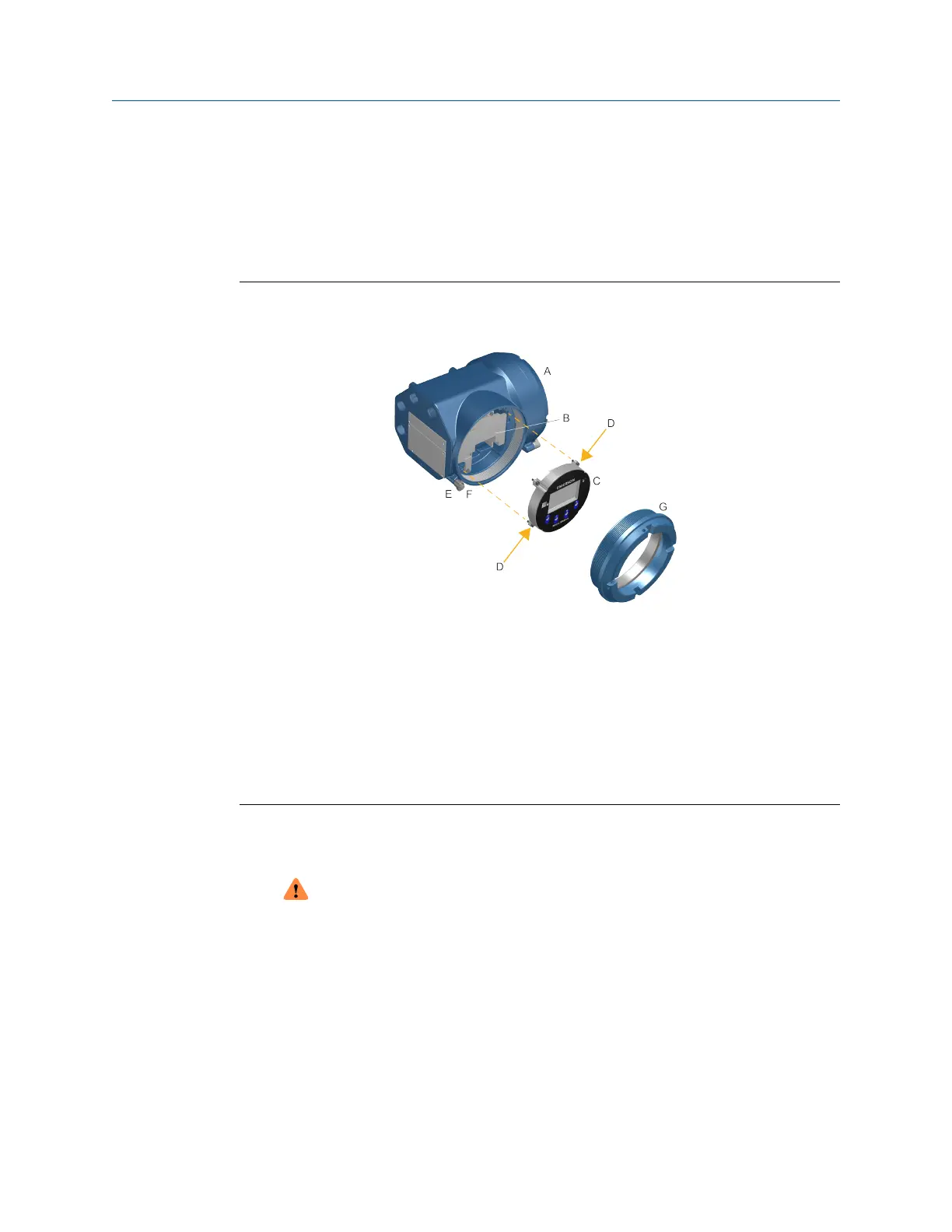
Figure 3-15: Display components
A. Transmitter housing
B. Sub-bezel
C. Display module
D. Display screws
E. End-cap clamp
F. Cap screw
G. Display cover
Procedure
1. Shut off power to the unit.
WARNING
If the transmitter is in a hazardous area, wait five minutes after disconnecting the
power. Failure to do so could result in an explosion causing death or injury.
2. Loosen and rotate the end cap clamp so that it does not interfere with the cover.
3. Turn the display cover counterclockwise to remove it from the main enclosure.
4. Carefully loosen the captive display screws while holding the display module in
place.
5. Carefully pull the display module out of the main enclosure.
6. Rotate the display module to the desired position.
Mounting and sensor wiring Installation Manual
April 2022 MMI-20027478
22 Micro Motion 5700 Transmitters with Configurable Inputs and Outputs