tape two to three layers deep. Wrap the tape in the opposite direction that the male
threads will turn when inserted into the female conduit opening.
□ Mount the meter in a location and orientation that satisfies the following conditions:
— Allows sufficient clearance to open the transmitter housing cover. Install with 8 in
(203 mm) to 10 in (254 mm) clearance at the wiring access points.
— Provides clear access for installing cabling to the transmitter.
— Provides clear access to all wiring terminals for troubleshooting.
2.2 Additional considerations for retrofitting
existing installations
□ The transmitter installation may require 3 in (76 mm) to 6 in (152 mm) of additional
wiring for the input/output and power connections. This length would be in addition to
the currently installed wiring. Confirm you have the additional wiring necessary for the
new installation.
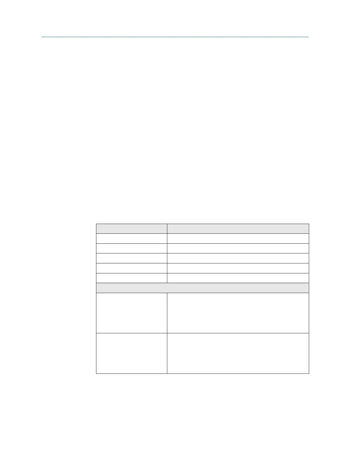
□ Before removing the existing transmitter, be sure to record the configuration data for
the currently installed transmitter. At initial startup of the newly installed transmitter,
you will be prompted to configure the meter via a guided setup.
Record the following information (if applicable):
Variable
Setting
Tag
Mass flow units
Volume flow units
Density units
Temperature units
Channel configuration
mA Outputs 1 — Power (internal or external):
— Source:
— Scaling (LRV, URV):
— Fault action:
mA Outputs 2 (optional) — Power (internal or external):
— Source:
— Scaling (LRV, URV):
— Fault action:
Planning Installation Manual
April 2022 MMI-20027478
8 Micro Motion 5700 Transmitters with Configurable Inputs and Outputs