2. If the primary mA Output is producing a fixed value of 4 mA, ensure that mA Output Action (Loop
Current Mode) is enabled.
For all HART addresses except 0, mA Output Action must be enabled to allow the primary mA output
to report process data.
3. Refer to the wiring diagrams in the installation manual and verify that the primary mA Output is
correctly wired for HART support.
4. Ensure that the output is powered.
5. Check for electrical problems at the transmitter terminals.
a) Disconnect the primary mA Output wires from the transmitter's MAO1 terminals.
b) Wire and power the MAO1 terminals as shown in the following figure.
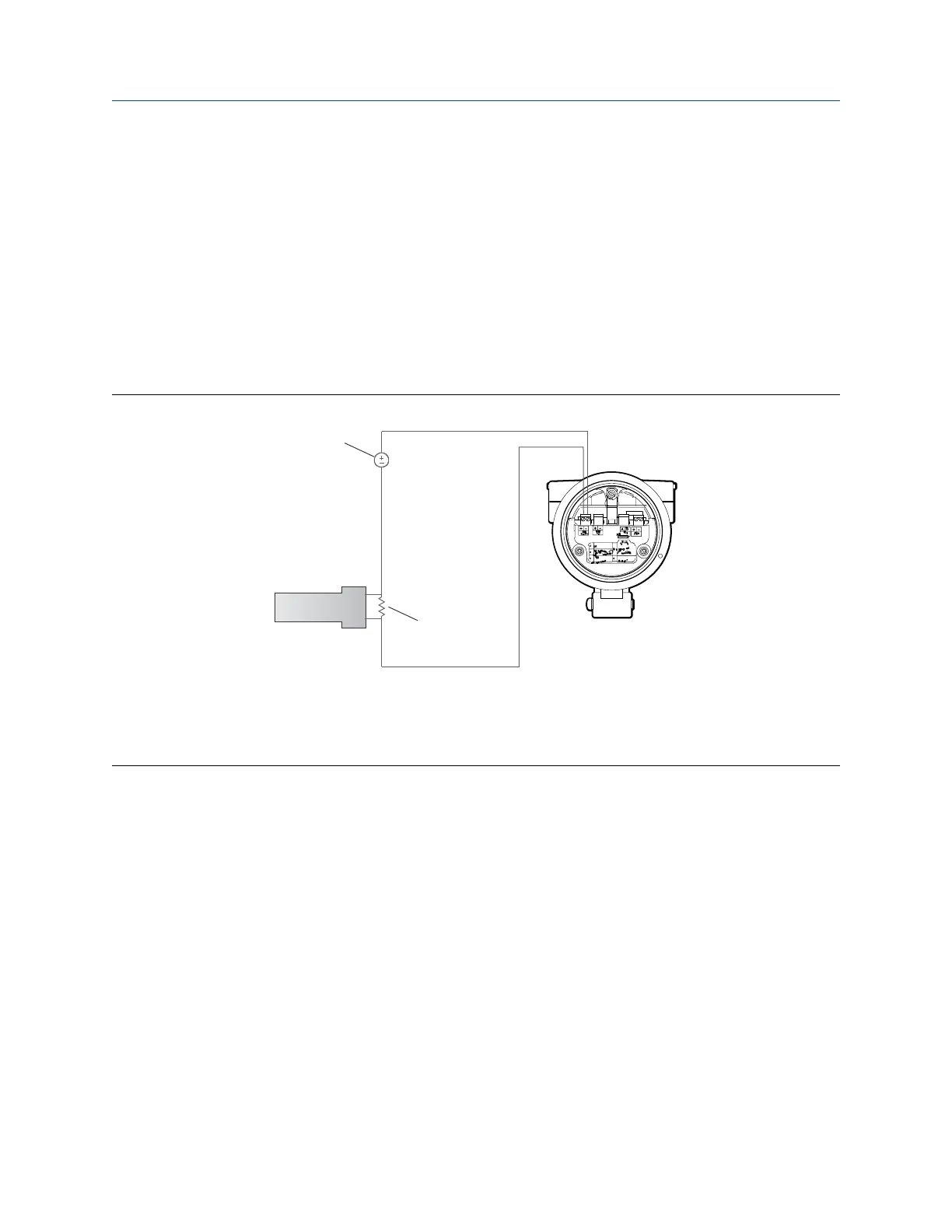
Figure 14-2: Wiring and power to test terminals
A. Voltmeter
B. 250–600 Ω resistance
C. External power supply
D. Transmitter with end-cap removed
c) Using a voltmeter, check the voltage drop across the resistor.
For a 250 Ω resistor, 4–20 mA = 1–5 VDC. If the voltage drop is less than 1 VDC, add resistance
to achieve a voltage drop within the required range.
d) Connect a field communicator directly across the resistor and attempt to communicate (poll).
If this test fails, the transmitter may need service. Contact Micro Motion.
Related information
Configure basic HART parameters
Using the field communicator with the transmitter
Configuration and Use Manual Troubleshooting
MMI-20020954 March 2021
Configuration and Use Manual 141