10 Integrate the meter with the control
system
10.1 Configure Channel B
ProLink III Device Tools → Configuration → I/O → Channels
Field communicator Configure → Manual Setup → Inputs/Outputs → Channels → Channel B
Depending on your device, you can configure Channel B to operate as either an mA output or a discrete
output.
Prerequisites
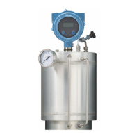
The configuration of Channel B must match the wiring. See the installation manual for your device.
To avoid causing process errors:
• Configure Channel B before configuring the mA output or discrete output.
• Before changing the channel configuration, ensure that all control loops affected by the channel are under
manual control.
Restriction
You cannot configure Channel B on the following devices: SGM TPS or SGM Fixed. On these devices, Channel B
always operates as a TPS output.
Procedure
Set Channel B as desired.
Option
Description
mA output Channel B will operate as the secondary mA Output.
Discrete output Channel B will operate as a discrete output.
10.2 Configure the mA Output
The mA Output is used to report the configured process variable. The mA Output parameters control how the
process variable is reported.
The SGM mA device has two mA Outputs: Channel A and Channel B. Both outputs are fully configurable.
The SGM DO device has one mA Output: Channel A. The output is fully configurable.
The SGM TPS device has one mA Output: Channel A. The output is fully configurable.
The SGM Fixed device has one mA Output: Channel A. The output is not configurable.
Configuration and Use Manual Integrate the meter with the control system
MMI-20020954 March 2021
Configuration and Use Manual 85