Design and function SPECORD PLUS
14
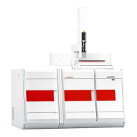
Figure6 SPECORD 50 PLUS general design
1 VIS lamp 2 UV lamp
3 Toric mirror 4 Filter wheel
5 Entrance slit (hidden) 6 Concave grid
7 Exit slit 8 Spherical mirror
9 Plane mirror 10 Quartz plate
11 Comparison channel receiver 12 Sample chamber
13 Cell 14 Measuring location for opaque samples
15 Measuring channel receiver
The spectrometer system with the filter wheel, concave grid and slit group elements
shown above functions as a monochromator.
The following filters are mounted on the filter wheel:
Filter Function
Colored glass filters Suppression of the undesired radiation in the monochromator
Holmium filter Standard for the automatic recalibration of the wavelengths
2 empty slots Allows undispersed light to pass through
Locking cone Dark signal measurement
The inlet and outlet slits of the spectrometer system are mounted on the slit carrier. The
following spectral slit widths are implemented in this manner on the various device
types:
Device Slit widths
SPECORD 50 PLUS 1.4nm
SPECORD 200 PLUS 1.4nm
SPECORD 210/250
PLUS
0.2; 0.5; 1; 2; 4nm.
The imaging grid disperses the incoming light and fans out the spectrum.
Computer-controlled step motors drive the filter wheel, slit carrier and linear actuator
for the grid movement. The low number of moving parts in the spectrometer system
leads to high reliability of the optical parameters of the SPECORD PLUS.

 Loading...