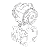
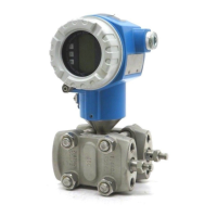
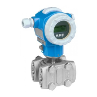
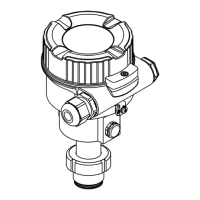
Deltabar FMD71, FMD72
12 Endress+Hauser
Output
Output signal
4 to 20 mA with superimposed digital communication protocol HART 6.0, 2-wire
Operation Internal + LCD External
1)
+ LCD Internal
on on
off off
damp.
damp.
Display Display
Sensor Sensor
HART HART
R R
FIELD COMMUNICATION PROTOCOL FIELD COMMUNICATION PROTOCOL
SW /min
SW /min
E
+
–
E
+
–
A0021280
Order code option
2)
4 5 8
1) In the case of the T17 transmitter housing, the operating keys are always arranged internally on the electronic insert.
2) Product Configurator order code for "Display, operation:"
Signal range 4 to 20 mA
3.8 mA to 20.5 mA
Signal on alarm 4 to 20 mA
As per NAMUR NE43
• High alarm (factory setting: 22 mA): can be set from 21 to 23 mA
• Hold measured value: last measured value is held
• Min. alarm: 3.6 mA
Maximum load
In order to guarantee sufficient terminal voltage in two-wire devices, a maximum load resistance R
(including line resistance) must not be exceeded depending on the supply voltage U
0
of the supply
unit. In the following load diagrams, observe the position of the jumper and the explosion protection:
U – 12 V
U – 13 V
R
L
max
23 mA
23 mA
£
30
20
12
U
[V]
40 45
1217
1435
783
348
[ ]W
[ ]W
R
L
max
R
L
max
30
20
13
40 45
1174
1391
739
304
Test
Test
£
3
A B
1
3
2
1
2
R
L
max
U
[V]
A0017533
A Jumper for 4 to 20 mA test signal set to "Non-test" position
B Jumper for 4 to 20 mA test signal set to "Test" position
1 Power supply for II 1/2 G Ex ia, FM IS, CSA IS
2 Power supply for devices for the non-hazardous area, 2 G Ex d, 3 G Ex nA, FM XP, FM NI, CSA XP, CSA dust
ignition-proof
3 R
Lmax
maximum load resistance
U Supply voltage
When operating via a handheld terminal or via a PC with an operating program, a minimum
communication resistance of 250 Ω must be taken into account.

 Loading...


