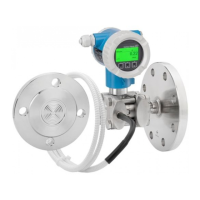
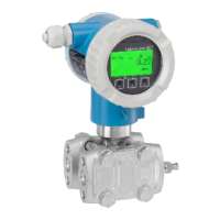
Deltabar FMD71, FMD72
Endress+Hauser 15
Power supply
L
WARNING
Electrical safety is compromised by an incorrect connection!
‣
In accordance with IEC/EN61010 a separate circuit breaker must be provided for the device .
‣
When using the measuring device in a hazardous area, installation must also comply with the
relevant national standards and regulations as well as the safety instructions or installation or
control drawings.
‣
All explosion protection data are given in separate documentation which is available upon
request. The Ex documentation is supplied as standard with all devices approved for use in
explosion hazardous areas.
‣
Devices with integrated overvoltage protection must be grounded.
‣
Protective circuits against reverse polarity, HF influences and overvoltage peaks are integrated.
Terminal assignment
4... 20mA
Test
Test
Test
4... 20mA Test
1
8
6
7
2
3
4
5
A0019989
1 Housing
2 Supply voltage
3 4 to 20 mA
4 Devices with integrated overvoltage protection are labeled "OVP" (overvoltage protection) here.
5 External ground terminal
6 4 to 20 mA test signal between positive and test terminal
7 Internal ground terminal, minimum supply voltage = 12 V DC, jumper is set as illustrated in the diagram.
8 Jumper for 4 to 20 mA test signal,
Supply voltage
Electronic version Jumper for 4 to 20 mA test signal in
"Test" position (delivery status)
Jumper for 4 to 20 mA test signal
in "Non-test" position
4 to 20 mA HART, version for
non-hazardous areas
13 to 45 V DC 12 to 45 V DC
Measuring a 4 to 20 mA test signal
A 4 to 20 mA test signal may be measured via the positive and test terminal without interrupting
the measurement. The minimum supply voltage of the device can be reduced by simply changing the
position of the jumper. As a result, operation is also possible with a lower supply voltage. To keep the
measured error below 0.1 %, the current measuring device should exhibit an internal resistance of
<0.7Ω. Observe the position of the jumper in accordance with the following table.

 Loading...