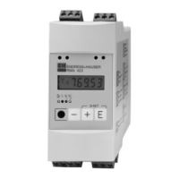
Nivotester FTR525
Endress+Hauser
29
Commissioning
Example:
018
1M
2 1 1 2
2
1
3
4
Max. detection range
Set detection range
Current measured value within the
set detection range
Current measured value at the
limit of the set detection range
Current measured value outside
of the set detection range
17 Manualadjustmentlowerlimit(LL)levellimitdetectiondisplaywithexamples
1 Setdetectionrange(=0-100%ofsignaloutput)
2 Lowerlimit(adjustableusingthisfunction)
3 Percentagevalueforthelowerlimitrelativetothemaximumpossibledetectionrange
4 Currentmeasuredvalue
The microwave barrier is optimally adjusted to match the application when the lower
detection limit (function 2112) corresponds to the minimum signal strength and the
upper detection limit (function 2113) corresponds to the maximum signal strength.
detection range
18 Optimaladjustment
Procedure for optimal adjustment:
value.
Manually adjust the upper limit (function 2113
maximum measured value.
The detection range can also be set to be lower or higher, for example if a turndown of the
signal output is desired.
8�4�1�3 Manual adjustment upper limit (UL) level limit detection
Application
2000
→
Sensor
2100
→
Limit detection
2110
→
Manual adjustment UL
2113
range 0 to 100 %). To assist with adjustment, the current measured value is shown
alongside the set detection range (see example function 2112).

 Loading...
