Do you have a question about the Endress+Hauser RMA 422 and is the answer not in the manual?
Guidelines for the correct application and use of the process transmitter, emphasizing safety and compliance.
Explanation of symbols used in the manual: Hint, Attention, Warning.
Details requirements for skilled personnel performing installation and setup of the unit.
Diagram illustrating the main components and functions of the process transmitter.
Key considerations for installing the unit, such as vibration, temperature, and heat sources.
Provides detailed dimensions of the unit's housing for installation planning.
Diagram and table detailing the function of each terminal on the unit.
Information on connecting the unit to AC or DC power supplies, including safety precautions.
Instructions for connecting various types of sensors, including active current sources and loop-powered transmitters.
Instructions for setting up and connecting analogue output signals (current or voltage).
Details on connecting the alarm set point relays for fault and alarm conditions.
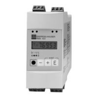
Identification and explanation of the unit's display components, LEDs, and buttons.
Step-by-step guide on navigating the unit's operating menu for configuration and settings.
Function for quickly setting alarm set points and fault conditions by bypassing the main operating menu.
Function for quickly displaying individual measurements or reference values on the unit.
Detailed overview of the unit's parameter structure and menu groups for configuration.
Configuration settings for the unit's analogue input channels, including range and damping.
Detailed parameters for sensor scale, decimal points, and measured value offset.
Configuration of the mathematics channel for signal combination of input values using formulas.
Parameters for operator, curve selection, decimal points, and factors for the mathematics channel.
Parameters for total decimal point, offset, and linearisation points for the mathematics channel.
Setting the reference value for the display, selecting the signal source.
Configuration of analogue output signals, including reference value, output range, and scale.
Configuration of alarm set points, operating modes, and hysteresis for fault monitoring.
Parameters for reset threshold, hysteresis, time delay, and time trend monitoring for alarms.
Explanation of hysteresis dependence on thresholds and trend monitoring for alarms.
Examples of alarm operation, ALAN feature, and switch time delay for fault monitoring.
Setup of linearisation points, including number of points, deletion, and display options.
Configuration of operating parameters such as alternating pump control and user codes.
Setup of user codes, set point protection, program name, software version, and test functions.
Parameters related to customer service and release codes for unit configuration.
Example of measuring tank volume using pressure sensors and the process transmitter.
Steps involved in calculating tank volume: sensor transmission and differential pressure calculation.
Allocating volume using linearisation, setting display and alarm parameters for the example.
List of system fault messages, their causes, effects, fault codes, and solutions.
Additional fault messages related to display, analogue outputs, and hardware issues.
Fault messages for analogue outputs, over/under range, and signal monitoring issues.
Fault messages related to analogue output values and input signal conditions.
Comprehensive technical specifications covering application, construction, inputs, and outputs.
Technical data on output, relays, alarm set points, mathematics function, power, and accuracy.
Technical data on installation, ambient conditions, EMC, safety, and mechanical construction.
Technical data on display, operating level, certifications, and approvals.
Comprehensive list of all parameters, their addresses, and settings for the process transmitter.
| Brand | Endress+Hauser |
|---|---|
| Model | RMA 422 |
| Category | Transmitter |
| Language | English |