RMS621 Operation
Endress+Hauser 23
5Operation
5.1 Display and operating elements
!
Note!
Depending on the application and version, the Flow and Energy Manager offers a wide range of
configuration options and software functions.
Help text is available for nearly every operating item to assist when programming the device. This
help text can be called up by pressing the "?" button. (The help text can be called up in every menu).
Please note that the configuration options described below refer to a basic unit (without extension
cards).
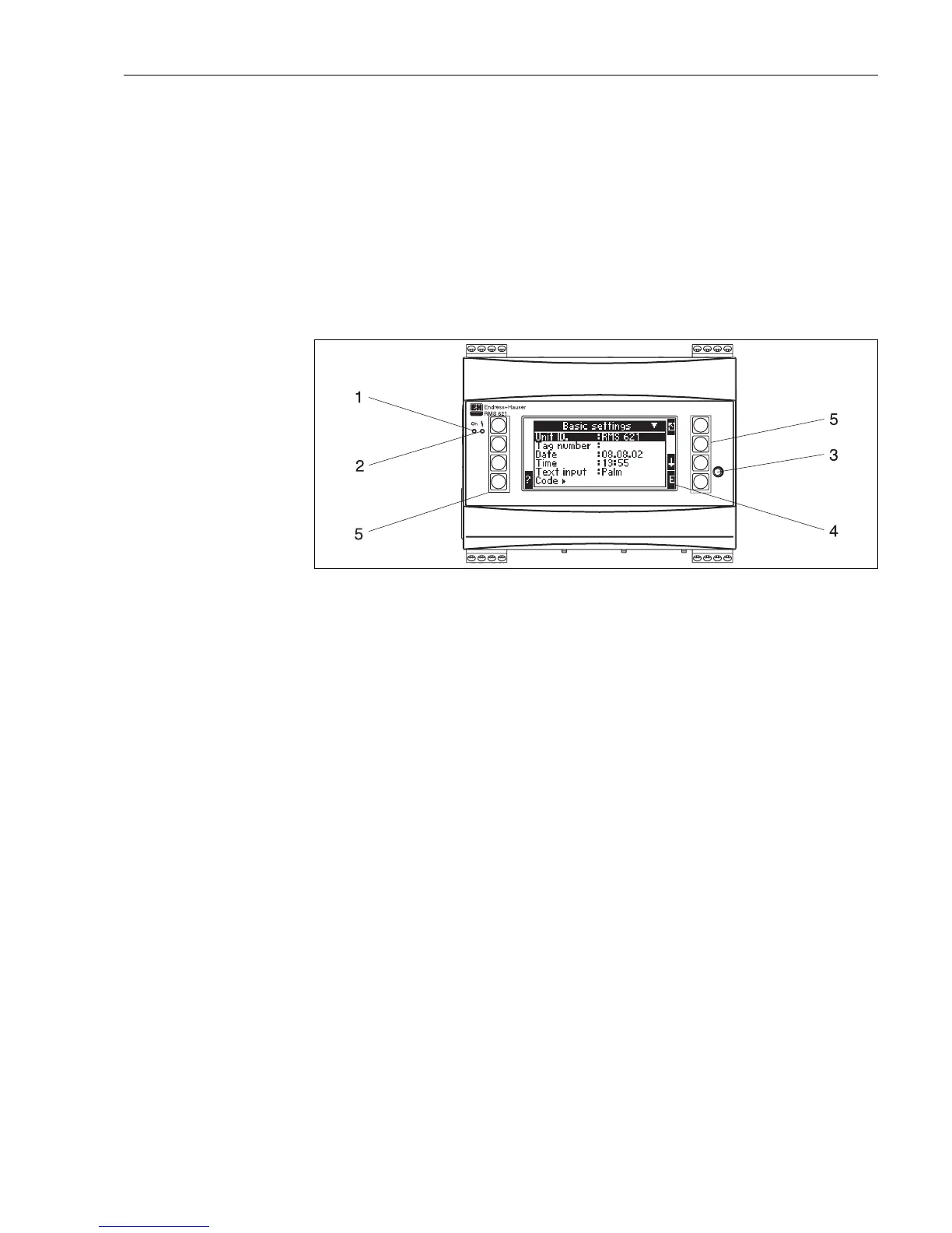
Fig. 16: Display and operating elements
Item 1: operating display: LED green, lights up when supply voltage applied.
Item 2: fault indicator: LED red, operating status as per NAMUR NE 44
Item 3: serial interface connection: jack socket for PC connection for device configuration and measured value read-out
with the PC software
Item 4: display 132 x 64 dot-matrix display with dialog text for configuring as well as measured value, limit value and fault
message display. Should a fault occur, the background lighting changes from blue to red. The size of the characters
displayed depends on the number of measured values to be displayed (see Section 6.3.3 ’Display configuration’).
Item 5: input keys; eight soft keys which have different functions, depending on the menu item. The current function of
the keys is indicated on the display. Only the keys which are required in the operating menu in question are assigned with
functions or can be used.