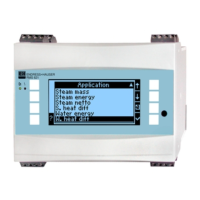
RMS621
Endress+Hauser 3
Brief operating instructions
"
Caution!
The information contained in these Operating Instructions serves as a guide to help you commission
your device easily, i.e. the most important settings are listed here but special functions (e.g. tables,
corrections etc.) are not.
Configuring a measurement - Set-up example
Example 1: Steam heat (or steam mass)
Sensors: DPO10 (orifice), Cerabar T, TR 10
1. Connect device to the power source (terminal L/L+, 230 V)
2. Press any key → Setup (all parameters)
3. Basic set-up
Date-time (set up date and time) Æ
Z
Select system eng. units (select metric or American)
4. Flow inputs (flow 1)
Flow meter: Differential pressure
Diff. device: Orifice corner tap
Signal: 4 to20 mA
Terminals: Select A10 and connect DP transmitter to terminals: A10(-)/82(+) (because of
passive signal)
Curve: linear (also set up linear curve at the DP transmitter)
Set up start- and end-value (in mbar!)
Tube data: enter internal tube diameter and diameter ratio (ß) as found on the maufacturers
data sheet.
"
Caution!
If tube data is not known, for flow meter: select operating volume
Curve: linear (set up square rooted curve on the DP transmitter)
Set up start- and end-values (m
3
/h)
5. Pressure input (Pressure 1)
Signal type: e.g. 4 to 20 mA
Terminals: Select A110 and connect Cerabar T to terminals: A110(-)/A83(+) (passive signal)
Type: Select absolute (-pressure measurement) or relative (-pressure measurement)
Set up start- and end-values of the pressure transmitter Æ
Z
6. Temperature inputs (temp. 1.1)
Signal type: Pt100
Sensor type: 3- or 4-wire
Select terminals E1-6 and connect Pt100 Æ
Z
Æ
Z
.
7. Application
Application 1: Steam heat
Steam type: super heated steam
Allocate flow 1, pressure 1 and temp. 1.1 to the steam measurement.
Fig. 1: Temperature sensor connection, e.g. to input 1 (Slot E I)
Pos. 1: 4-wire input
Pos. 2: 3-wire input
Pos. 3: 3-wire input e.g. optional
temp. expansion card (Slot B I)

 Loading...