Operating Instructions SS2100i-2 TDLAS Gas Analyzer
12 Endress+Hauser
for operational instructions. The firmware version for each analyzer is also listed on the analyzer calibration
certificate.
2.5 Getting familiar with the analyzer
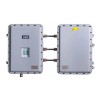
The SS2100i-2 analyzer consists of two connected enclosures in a standard cable-coupled configuration, as shown in
the figure below.
Fig 5. Cable-coupled analyzer configuration
The left enclosure (electronics enclosure) contains the control electronics and input/output electrical connections, as
shown below. The right enclosure (sample cell enclosure) contains the sample cell and heater, as shown in Fig 8.
Components on an 8 or 28 m sample cell panel enclosure , Fig 9. Components on a 0.8 m sample cell panel assembly,
or Fig 10. Components on a 0.1 sample cell panel enclosure. The keypad and LCD display on the cover of the
electronics enclosure are the user interface to the analyzer. Power and signal connections are made via access ports
on the bottom of the electronics enclosure. Tube fittings on the right side of the sample cell enclosure are for sample
supply and return connections. Both enclosures are mounted on a Unistrut
®
frame.

 Loading...


