Contact Service for any questions related to leak testing. Refer to Service → .
6.7 Flame arrestor replacement and safety
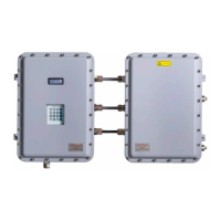
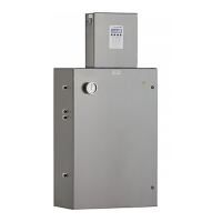
The analyzer system comes equipped with a protective covering over the flame arrestors and tubing that runs from
the analyzer electronics to the SCS. Refer to the analyzer system drawings to locate the protective enclosure for your
analyzer; the location of which can vary by customer configuration.
6.7.1 Tools required
•
7
/
16
in angle double open-end wrench
•
9
/
16
in angle double open-end wrench
• ⅞ in wrench
6.7.2 To replace the flame arrestors
1. Ensure all safety requirements have been met and any necessary protective gear and tools are being used.
Refer to Potential health effects → before removing insulation.
2. Purge the system following the instructions provided in steps 1 through 8 in Preparing the analyzer for shipment
or storage → .
3. Remove the screws holding the protective cover in place and lift the cover to remove from the enclosure.
4. Remove the insulation packed inside the enclosure and place in a clean, dry area.
Fig 45. Unpacking enclosure insulation
5. Disassemble the tubing using a
9
/
16
in wrench.

 Loading...


