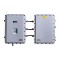
SS2100i-2 TDLAS Gas Analyzer Operating Instructions
Endress+Hauser 27
1. Connect the chassis ground to the marked upper right corner of the right-side enclosure.
2. Connect the chassis ground to the marked bottom left corner of the left-side enclosure.
3. Connect the system ground to the ground bus bar as shown in Fig 7. Components in SS2100i-2 electronics
enclosure during the electrical power connection.
4.7 Opening the analyzer enclosure covers
Care must be taken to avoid damaging the enclosure cover and body mating surfaces which form a machined
flame path (gap 0.05 mm, roughness 6 m). If the surfaces are damaged to the extent they no longer meet
the above specifications, please contact your Endress+Hauser service representative. Refer to 58.
4.7.1 To open an analyzer enclosure cover
1. Using an 8 mm hex key wrench or driver, remove each cover screw completely.
2. Place cover screws in a safe place to protect against damage or loss.
3. Gently open cover by pulling on the edge opposite the hinges.
4.8 Cable installation
To avoid potential damage, cable systems and accessories should be installed, so far as practicable, in positions that
will prevent them from being exposed to mechanical damage, to corrosion or chemical influences, to the effects of
heat and to UV radiation. Refer to the Description of Device Parameters → for more information.
4.8.1 Terminations
Connections shall be made in a manner consistent with the type of terminal, type of protection and not introduce
undue stress on the connections.
If multi-stranded and fine-stranded conductors are employed, the ends shall be protected against separation of the
strands, e.g., by means of cable lugs, core-end sleeves or by the type of terminal, but not by soldering alone.
The creepage distances and clearances shall not be reduced by the method in which the conductors are
connected to the terminals.
4.9 Cable glands
Certified compound barrier seal type glands and cables shall be used where appropriate in compliance with local
regulations.
The cable gland shall be selected to match the cable diameter. The use of sealing tape, heat-shrink tube or other
materials are not permitted to make the cable fit to the cable gland.
If an Ex “d” gland clamping by the sealing ring (compression) is used with braided or armored cable, it shall be the
type where the braid or armor is terminated in the gland and compression takes place on the inner cable sheath.
For flameproof enclosures, adapters shall not be used together with blanking elements.
Flameproof cable glands, adapters or blanking elements, having parallel threads may be fitted with a sealing washer
between the entry device and the flameproof enclosure provided that the applicable thread engagement is still
achieved after the washer has been fitted. Thread engagement shall be at least five (5) full threads. Suitable grease
may be used if it is non-setting, non-metallic and non-combustible and any earthing between the device and the
flameproof enclosure is maintained. Endress+Hauser recommends using STL8 screw thread lubricant or equivalent
on all screw thread and its taped opening. Refer to Application of gland lubricant.
Do not use this lubricant on exposed current-carrying parts.

 Loading...


