Installing Optional Mini-GBICs
3-4 Hardware Installation
Installation
ToinstallaMini‐GBICthathasanRJ45connector,refertoFigure3‐1;foraMini‐GBIC
withanMT‐RJconnector,refertoFigure3‐2;foraMini‐GBICwithanLCconnector,refer
toFigure3‐3;andproceedasfollows:
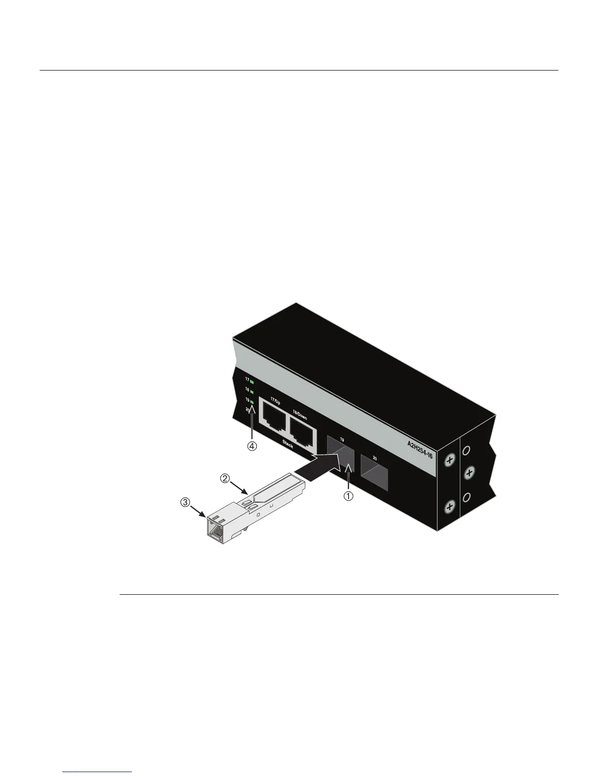
1. HoldtheMini‐GBICwiththetopsidepositionedasshown,andthe7‐pinedge
connectorfacingtheportslot.
2. AligntheMini‐GBICwiththeportslot.
3. IfyouareusingtheRJ45Mini‐GBICasinFigure3‐1,besurethereleasetabisinthe
up
position.
4. PushtheMini‐GBICintothe portslotuntiltheMini‐GBIC“clicks”andlocksinto
place.
Figure 3-1 Mini-GBIC with RJ45 Connector
1 SFP Slot 3 Release tab
2 Mini-GBIC
(MGBIC-02) 4 Link/Activity LED