Installing the Switch on a Flat Surface
3-8 Hardware Installation
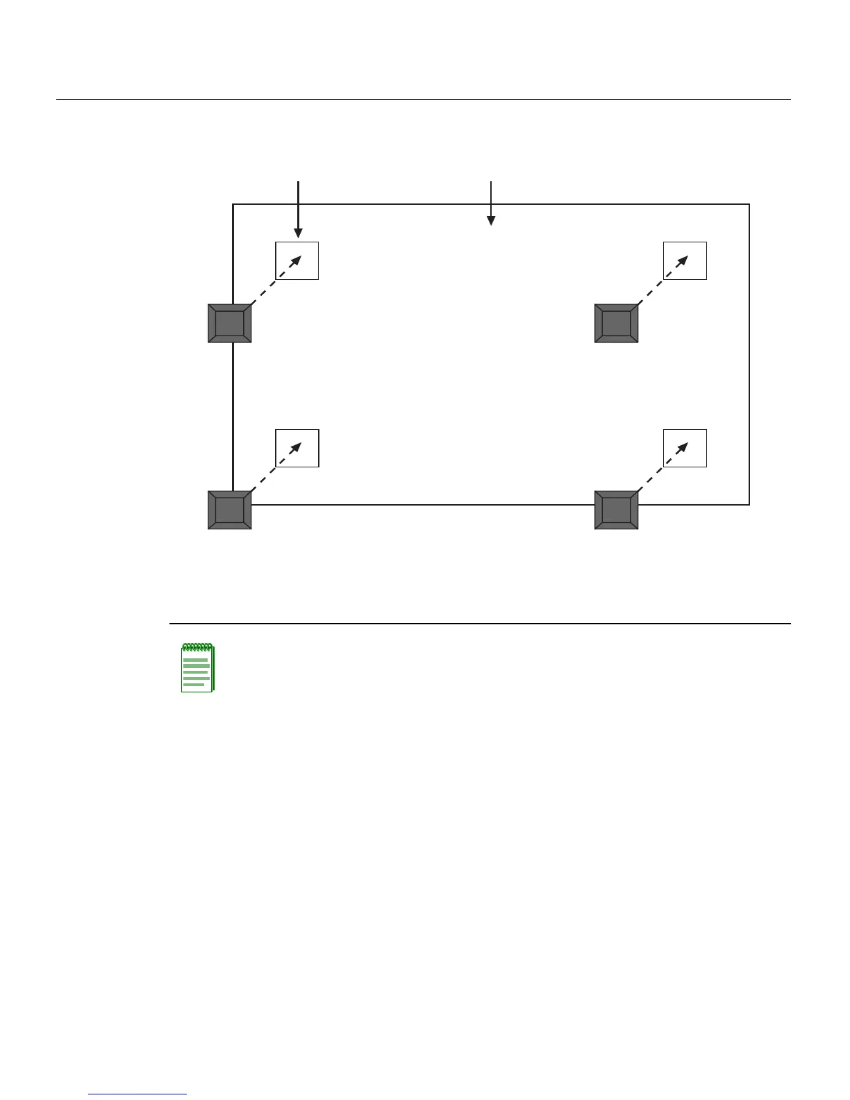
Figure 3-4 Chassis Bottom, Rubber Feet Placement
Guidelines for Flat Surface Installation
Locatetheswitchwithin152cm(5ft)ofitspowersourceandonasurfaceasshownin
Figure3‐5.
Atemperatureofbetween0°C(32°F)and40°C(104°F)mustbemaintainedatthe
installationsitewithfluctuationsoflessthan10°C(18°F)perhour.
Ifanoptionalredundantpowersystemisgoingtobeinstalledandconnectedtothe
14‐pinRedundantPowerSupplyinputconnectorontherearofthe
switch, refertothe
installationguideshippedwiththe redundantpowersystem.
1 Bottom of chassis as seen when chassis is
resting on its back
3 Rubber feet with adhesive backing
(four)
2 Locations to install the rubber feet (four locations)
Note: If a number of switches are being installed in a stack, repeat steps 1 through 4 to
install the rubber feet on each switch before continuing with the installation.
À
Á
ÂÂ
ÂÂ