Connecting AC and RPS-SYS Power
3-16 Hardware Installation
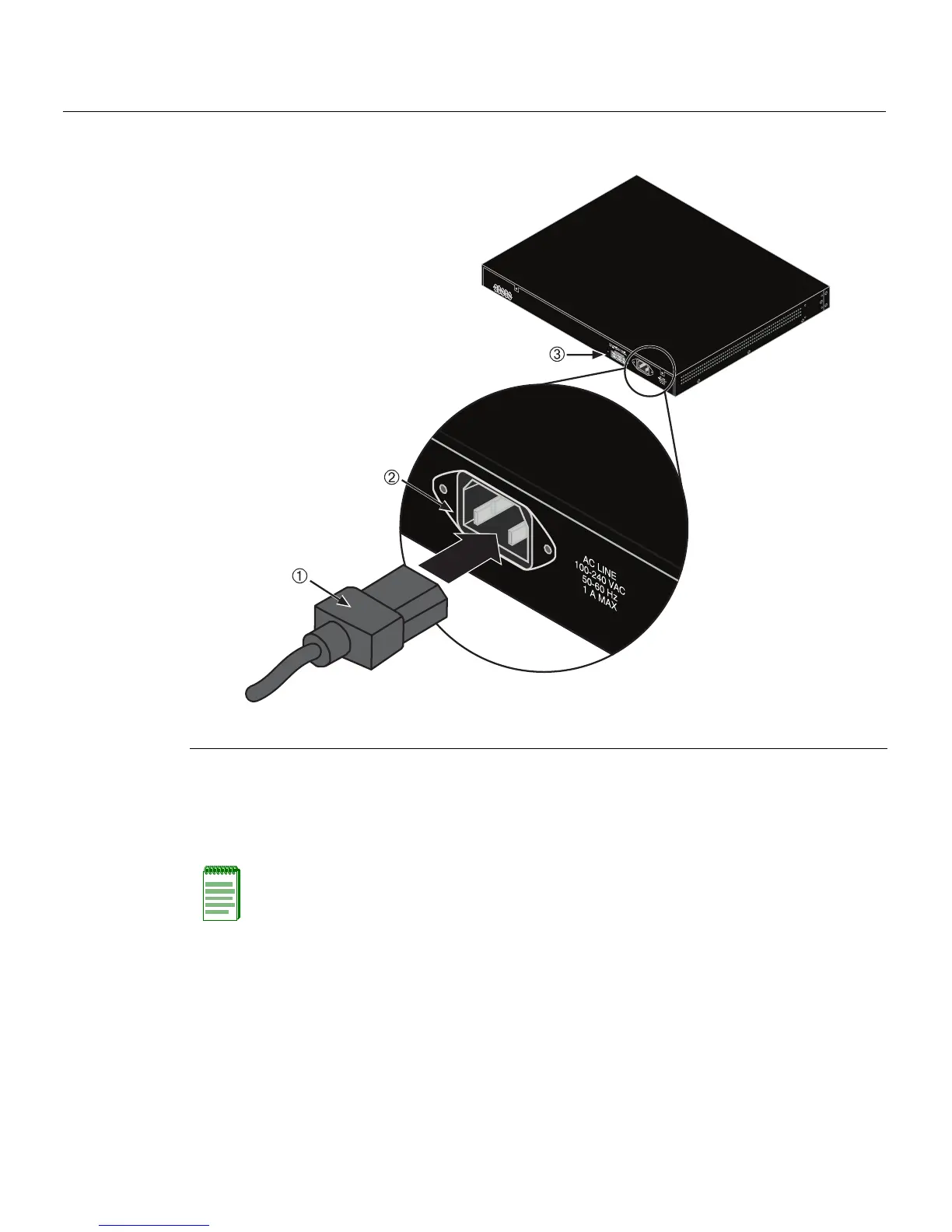
Figure 3-9 Switch Rear View
3. ObservethepowerCPULED(notshown),locatedonthefrontpanel.Duringthe
initialization,theCPULEDwillstartbyilluminatingsolidamber,thenstartblinking
green,thenblinkingamber,thenblinkinggreenagainuntiltheendofthe
initialization,andthenturnssolidgreen.
Iftheswitchisa
standaloneswitch,itwilltakeapp roximately30secondsforthe
switchtostartup.IftheswitchisastackManager,itcantakeupto3minutesormore
tostartup,dependingonthenumberofMemberswitchesinthestack.
1 AC power cord 2 AC power connector 3 Connector for external redundant power supply
Note: If the CPU LED illuminates solid red, there was a critical failure. For more
information about the LED indications and troubleshooting, refer to Chapter 4. If you need
additional help, contact Enterasys Networks. Refer to “Getting Help” on page 1-6 for
details.