36
IP1861EN - 2015-12-02
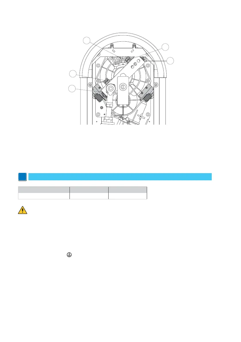
11. Limit switch adjustment (QIK4E only)
- Adjust the opening and closing position of the bar using the special screws [A].
- Adjust the opening and closing limit switches using the special cams [C] so that the switches
are activated approx. 3 mm before the mechanical stop [B].
Before connecting the power supply, make sure the plate data correspond to that of the
mains power supply.
An omnipolar disconnection switch with minimum contact gaps of 3 mm must be included in
the mains supply.
Check that upstream of the electrical installation there is an adequate residual current circuit
breaker and a suitable overcurrent cutout.
Use a H05RN-F 3G1.5 or H05RR-F 3G1.5 type electric cable and connect it to terminals L (brown)
and N (blue) inside the automation.
Connect the earth wire
.
Connection to the mains power supply, in the section outside the automation, is made with
independent channel and separated from the connections to the control and safety devices.
The channel must penetrate the automation through the holes on the base plate at least 50 mm.
Make sure there are no sharp edges that may damage the power supply cable.
Make sure the mains power conductors (230 V) and accessory power conductors (24 V) are
separated.
12. Electrical connections
N.B.: The electrical wiring and start-up of the gearmotors are shown in the control panel installation manuals.
i
A
A
B
C
C
QIK4E QIK7EH - QIK7YEH
Control panel E1A EL31R