38
REV. 09/2020
39
REV. 09/2020
DRIVING SYSTEM DRIVING SYSTEM
4 4
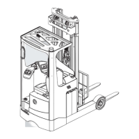
4.3 Drive Axle
4.3.1 Removal and Installation
Removal
- Power o the truck and remove the key;
- Remove the drive wheel; (see Section 4.1.1)
- Remove the mast; (see Section 8.1.1)
- Remove the cushion and floorboard, then
remove U, V and W cables on the drive
motor;
- Disconnect the connection between the drive
motor and main wiring cables;
- Remove the tubings on the brake;
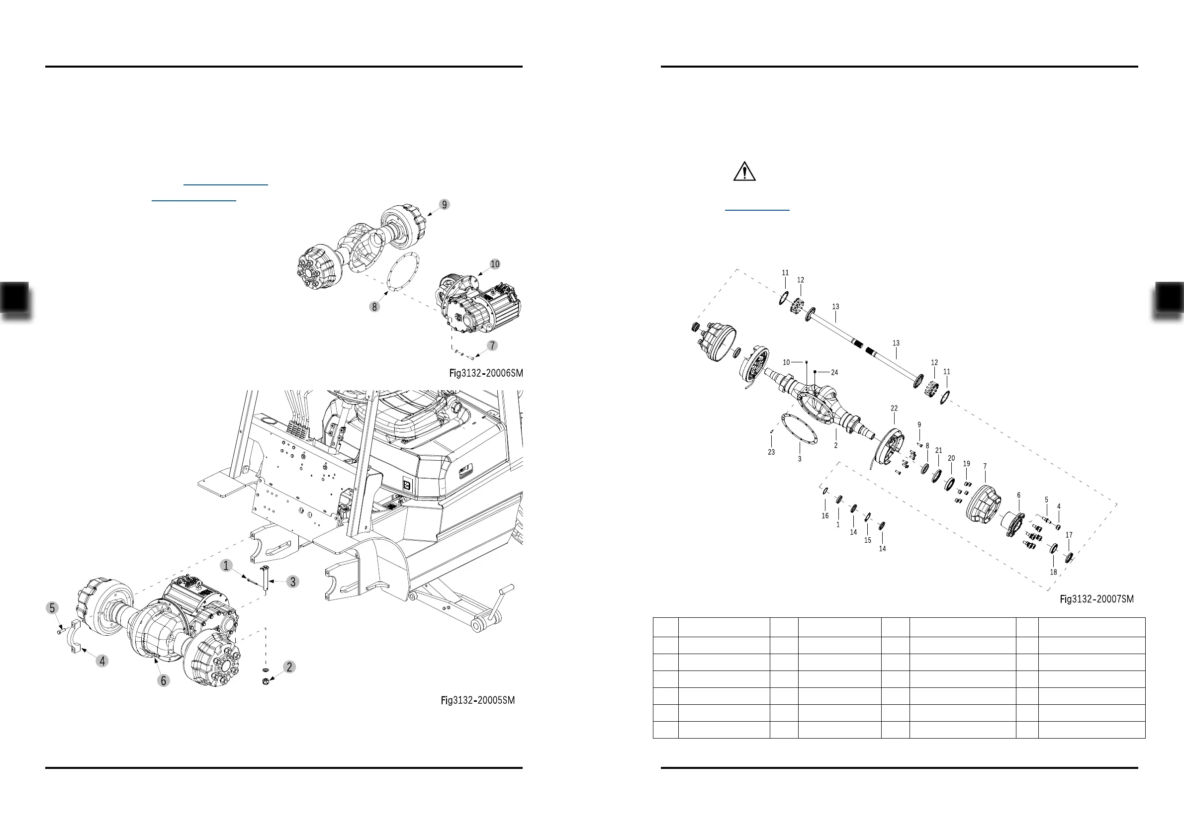
- Remove the cotter pin (1) and unscrew the
nut (2), then kncok out the pin shaft (3);
- Unscrew the four bolts (5) and remove
the bearing cap (4), then remove the drive
assembly (6) from the chassis;
- Loosen the oil drain plug and drain all gear
oil;
- Unscrew the twelve bolts (7) and remove the
seal (8), then dismantle the drive axle (9).
4.3.2 Component
Installation
- Install according to the reverse order of rem-
oval.
After installing the new drive axle, please add
gear oil (see Section 2.2.3 for specication and
lling amount).
CAUTION
No. Name No. Name No. Name No. Name
1 Seal Ring 7 Brake Hub 13 Axle Shaft 19 Nut
2 Axle Housing 8 Oil Seal 14 Nut 20 Bearing
3 Seal 9 Bolt 15 Thrust Ring 21 Lip Seal
4 Nut 10 Plug 16 O-ring 22 Brake Assembly R
5 Bolt 11 Gasket 17 Lip Seal 23 Parrallel Pin
6 Hub 12 Bolt 18 Bearing 24 Plug