42
REV. 09/2020
43
REV. 09/2020
DRIVING SYSTEM DRIVING SYSTEM
4 4
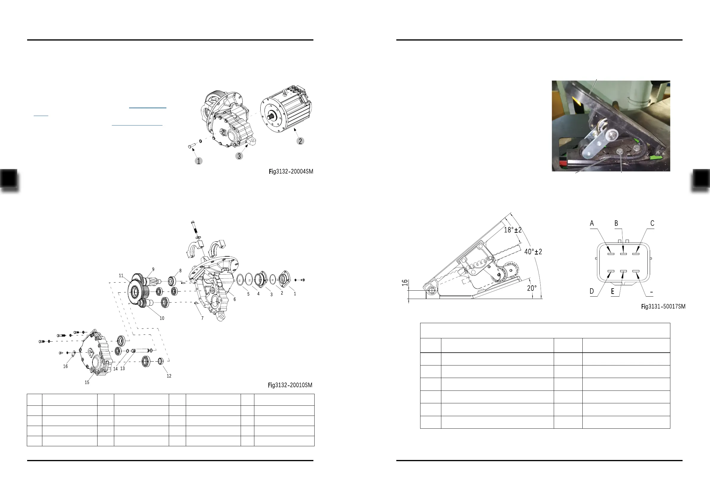
4.5 Gearbox
4.5.1 Removal and Installation
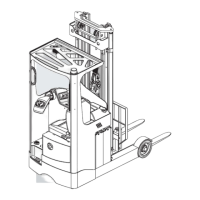
Removal (Fig3132-20004SM)
- Remove the drive assembly from the chassis
and dismantle the drive axle;(see Section
4.2.1)
- Dismantle the dierential; (see Section 4.4.1)
- Unscrew the ve bolts (1), remove the drive
motor (2) from the gearbox (3).
Installation
- Install according to the reverse order of rem-
oval.
4.5.2 Component
No. Name No. Name No. Name No. Name
1 Bearing Cap 5 Washer 9 Gear Shaft 13 Shaft
2 O-ring 6 Housing 10 Gear Shaft 14 O-ring
3 Bearing Cap 7 Pin 11 Dual Gear 15 Housing Cover
4 O-ring 8 Bearing 12 Seal Cap 16 Bracket
4.6 Accelerator Pedal
4.6.1 Removal and Installation
4.6.2 Interface Description
- Power o the truck and remove the key;
- Remove the cushion;
- Disconnect the connection between the
accelerator pedal wiring (1) and main wiring
harness ;
- Unscrew the two bolts (2) with wrench and
remove the accelerator pedal (3) from the
chassis;
- Install according to the reverse order of rem-
oval.
Interface Description
Pin Description Color Remark
A Pedal power supply Red 10-15Vdc
B Output signal White 0.2±0.1V~9±0.3V
C Pedal signal grounding Black -
D Pedal Switch - Positive Electrode Green Switch output (10-60V)
E Pedal switch output Grey Switch output
- - - -
1 2
3
Fig3132-50004SM