55
7
54
REV. 09/2020
BRAKE SYSTEM
6
6.2 Service Brake
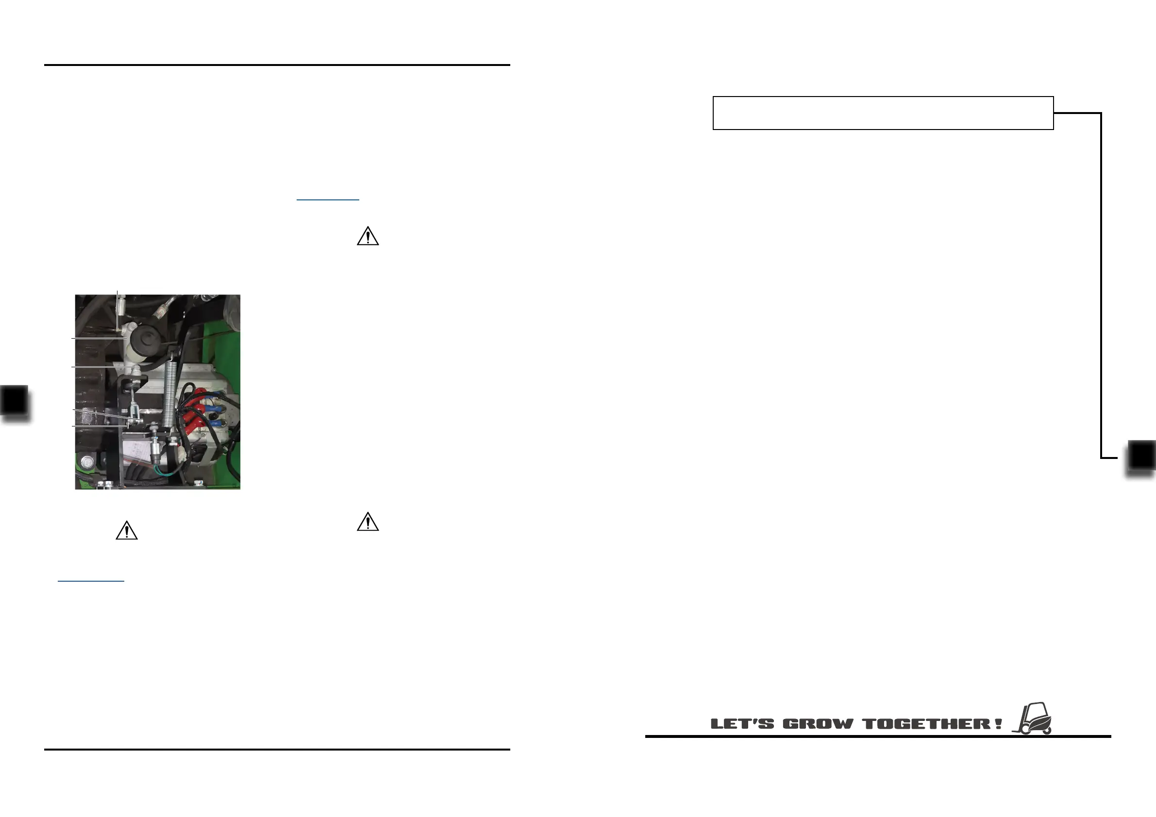
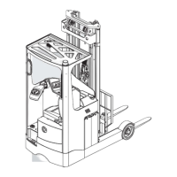
6.2.1 Removal and Installation
Removal
- Turn o the truck power and remove the key;
- Remove the cushion and open the oorboard;
- Loosen the nut (1) and remove the two tubings
on the brake master pump (5);
- Remove the cotter pin (2) on the pin shaft (3),
then knock out the pin shaft (3) from side;
- Unscrew the two bolts (4), then remove the
brake master pump (5) from the chassis.
- Install according to the reverse order of rem-
oval.
Installation
1
2
3
4
5
Fig3132-10002SM
When removing the tubing and brake pump, the
system will lose some brake uid, please refer
to Section 2.2.3 for supplementary adding of
brake uid.
CAUTION
After replacing the brake master cylinder or
tubings, the air within the entire brake pipeline
must be discharged.
6.2.2 Air Discharge / Adding Brake Fluid
-
-
Fill the oil cup with brake uid;
Press the brake pedal repeatedly until the
stepping pressure becomes heavy;
CAUTION
-
-
Open the vent on brake cylinder of drum
brake, press the brake pedal pressure to the
bottom, discharge the residual air from the
vent through high level of brake uid;
When there is flow of fluid running out of
the vent, it indicates that the air discharge is
completed, release the brake pedal and close
the vent.
During the entire process of operation, there
must always be brake uid in the oil cup.
-
Add brake uid into the oil cup until it lls 2/3
of the cup. Please apply as specified (see
Section 2.2.3 for specications).
CAUTION
7. HYDRAULIC SYSTEM