58
REV. 09/2020
59
REV. 09/2020
HYDRAULIC SYSTEM HYDRAULIC SYSTEM
7 7
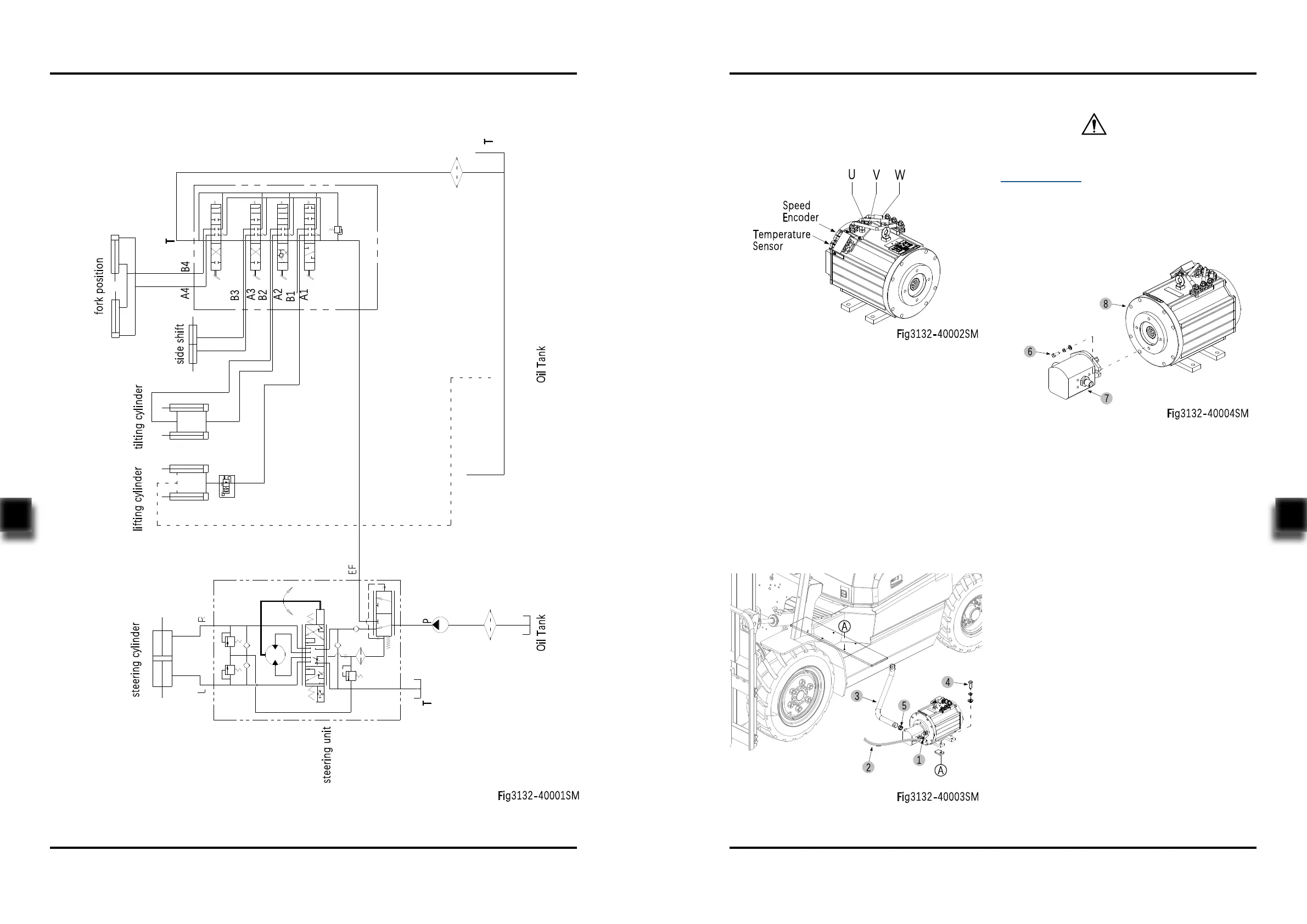
7.1.1 Hydraulic Schematic Diagram
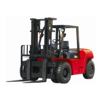
- Turn o the truck power and remove the key;
- Remove the AMP connector on the pump
motor and remove the cables U, V and W
from the pump motor;
- Loosen the tubing connector (1) with a
wrench, and then remove the tubing from the
gear pump;
- Loosen the clips on the clamp (5), remove the
pipe (3) from the gear pump;
- Unscrew the four bolts (4) and remove the
pump motor & gear pump assembly from the
chassis;
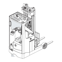
Removal
Installation
- Install according to the reverse order of rem-
oval.
When removing the tubing and pipe, the system
will lose some hydraulic oil, please refer to
Section 2.2.3 for supplementary adding of
hydraulic oil.
CAUTION
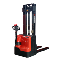
7.2 Pump Motor & Gear Pump
This truck obtains hydraulic power through the
AC pump motor.
- Unscrew the two bolts (6) and remove the
gear pump (6) from the pump motor (8).