REV. 09/2020 REV. 09/2020
MAST MAST
8 8
78 79
8.1.5 Built-in Side Shifter
8.1.5.1 Side Shifter Removal
-
-
-
Lower the mast to the bottom, press the eme-
rgency stop switch and disconnect the key
switch;
Block the truck wheel with wooden wedge;
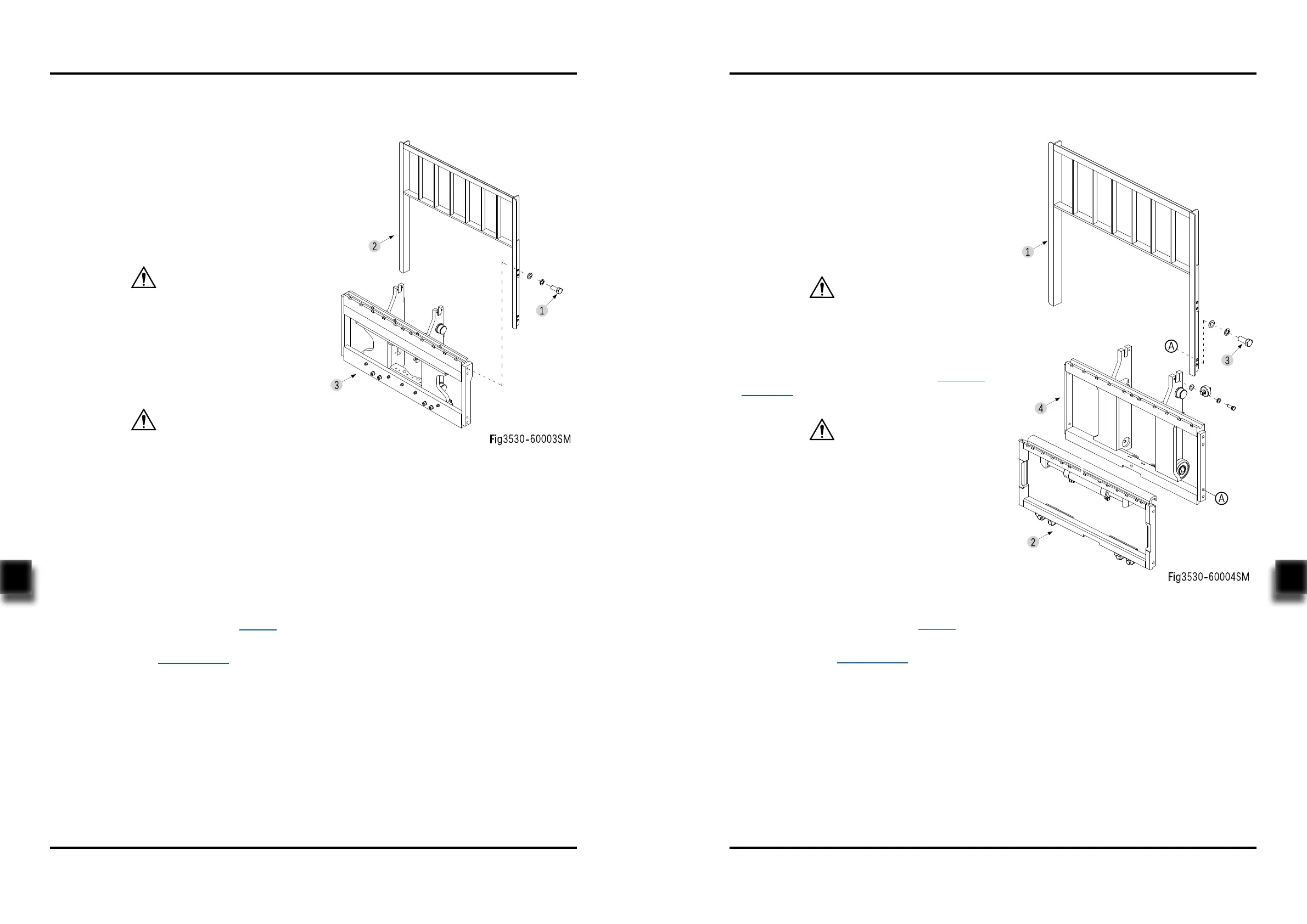
Unscrew the four bolts (1, Fig3530-60003SM),
remove the retaining shelf (2) from the built-in
side shifter (3);
Hydraulic oil may damage truck parts and cont-
aminate the environment. When removing joints
or tubings, place a clean container under it for
discharge of hydraulic oil.
- Remove the right shifting tubing (8, Fig3131-
60005SM) and left shifting tubing (7) from the
built-in side shifter;
Before going on with the next step, please
fix the side shifter properly first. Be sure to
avoid the falling of side shifter during removal,
resulting in personal injury.
- Remove the chain assembly and remove the
side shifter from inner mast.
8.1.5.2 Side Shifter Installation
-
-
-
-
-
Install the side shifter according to the rever-
se order of removal according to 8.1.5.1;
Add hydraulic oil of the same specifications
into the tank, see Section 2.2.3;
Pull out emergency stop switch and turn on
the key switch;
Repeat left shifting - right shifting operations
to discharge the air within the tubing and side
shift cylinder;
Check the hydraulic oil level and make sure
that the liquid is at standard level.
CAUTION
CAUTION
8.1.6 External Side Shifter
8.1.6.1 Side Shifter Removal
-
-
-
Lower the mast to the bottom, press the eme-
rgency stop switch and disconnect the key
switch;
Block the truck wheel with wooden wedge;
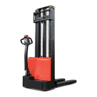
Unscrew the four bolts (3, Fig3530-60004SM),
remove the retaining shelf (1) from the exter-
nal side shifter (2);
Hydraulic oil may damage truck parts and cont-
aminate the environment. When removing joints
or tubings, place a clean container under it for
discharge of hydraulic oil.
-
Remove the right shifting tubing (8, Fig3131-
60005SM) and left shifting tubing (7) from the
built-in side shifter;
- Remove the external side shifter (2, Fig3530-
60004SM) from fork carriage (4).
8.1.6.2 Side Shifter Installation
-
-
-
-
-
Install the side shifter according to the rever-
se order of removal according to 8.1.6.1;
Add hydraulic oil of the same specifications
into the tank, see Section 2.2.3;
Pull out emergency stop switch and turn on
the key switch;
Repeat left shifting - right shifting operations
to discharge the air within the tubing and side
shift cylinder;
Check the hydraulic oil level and make sure
that the liquid is at standard level.
CAUTION
Before going on with the next step, please
fix the side shifter properly first. Be sure to
avoid the falling of side shifter during removal,
resulting in personal injury.
CAUTION